Cam type high-speed front-end machining machine

A processing machine and cam-type technology, which is applied in the direction of metal processing machinery parts, metal processing, metal processing equipment, etc., can solve the problems of lathe clamps that are not easy to clamp, long processing time, and low efficiency, so as to reduce manpower and increase product output , the effect of reducing the number of machines

Pending Publication Date: 2018-11-27
CHANGSHU SYNERGY AUTOMOBILE PARTS CO LTD
0 Cites 0 Cited by

AI-Extracted Technical Summary

Problems solved by technology

[0002] In the prior art, the processing of special bolt products is generally completed by machines such as lathes, but for large-scale products, the disadvantage of this processing method is ...

Abstract

The invention discloses a cam type high-speed front-end machining machine. According to the technical scheme, the cam type high-speed front-end machining machine comprises a base and is characterizedin that an inclined lathe bed is arranged on the base, a feeding mechanism, a clamping mechanism, a slidably arranged machine head and a discharge mechanism; the feeding mechanism comprises a feedingplate; the clamping mechanism comprises a clamping block facing the feeding plate; the machine head comprises a first motor and a power head connected with the first motor, and the power head is connected with a cutter; a second motor is arranged on the base, a reducer is arranged on the inclined lathe bed, the second motor drives the reducer to rotate through a synchronous belt and a synchronouswheel, the reducer is connected with a cutter feeding cam and a feeding cam, the cutter feeding cam is connected with a guide wheel, the guide wheel is connected with the clamping block, the feeding cam is connected with a push rod, and the base is further provided with a power lifting mechanism capable of driving the machine head to slide on the inclined lathe bed. The cam type high-speed front-end machining machine is high in production efficiency and capable of reducing potential safety hazards.

Application Domain

Large fixed membersMetal working apparatus

Technology Topic

CamEngineering +2

Image

  • Cam type high-speed front-end machining machine
  • Cam type high-speed front-end machining machine

Examples

  • Experimental program(1)

Example Embodiment

[0013] The present invention will be further described below in conjunction with the drawings.
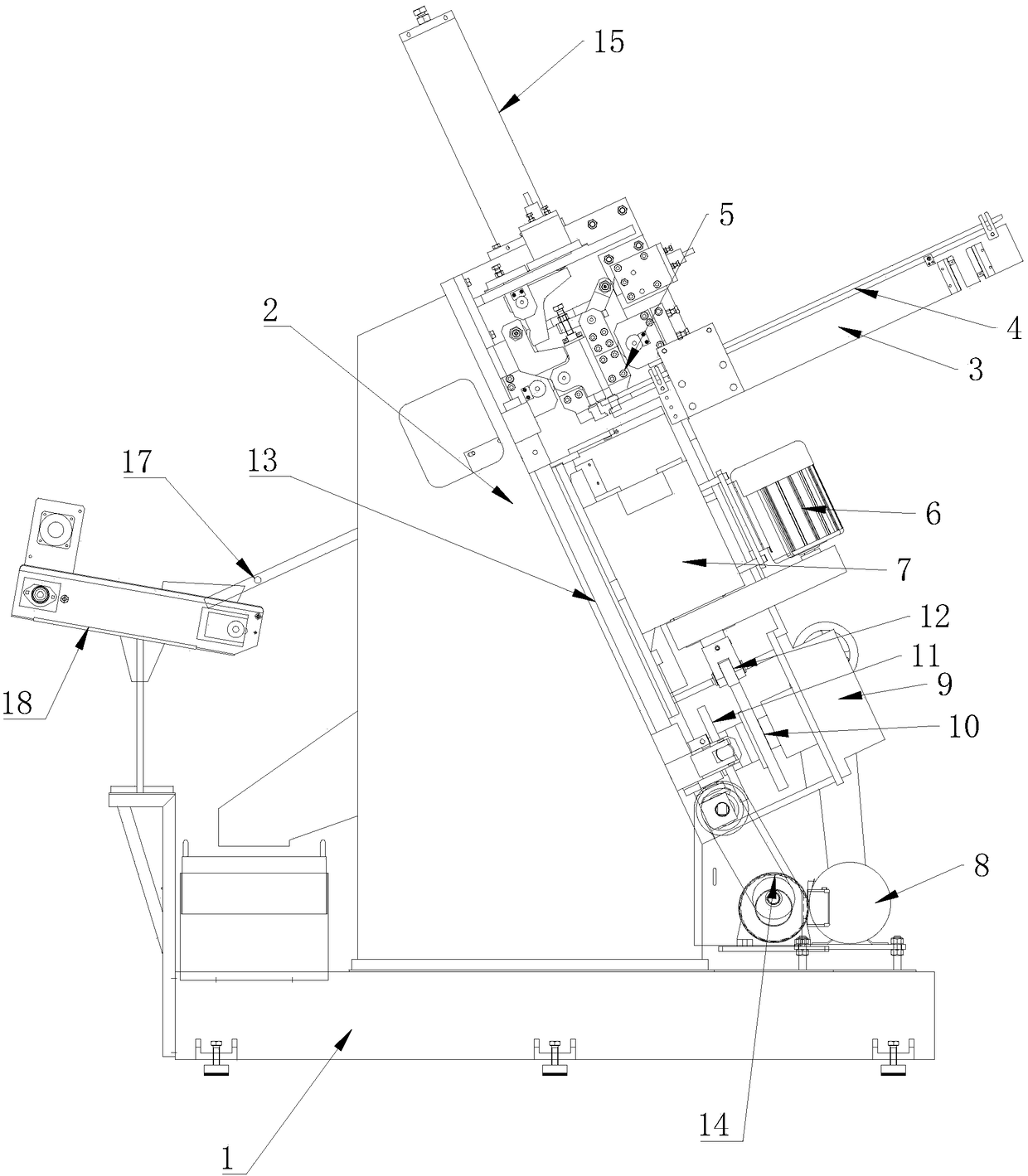
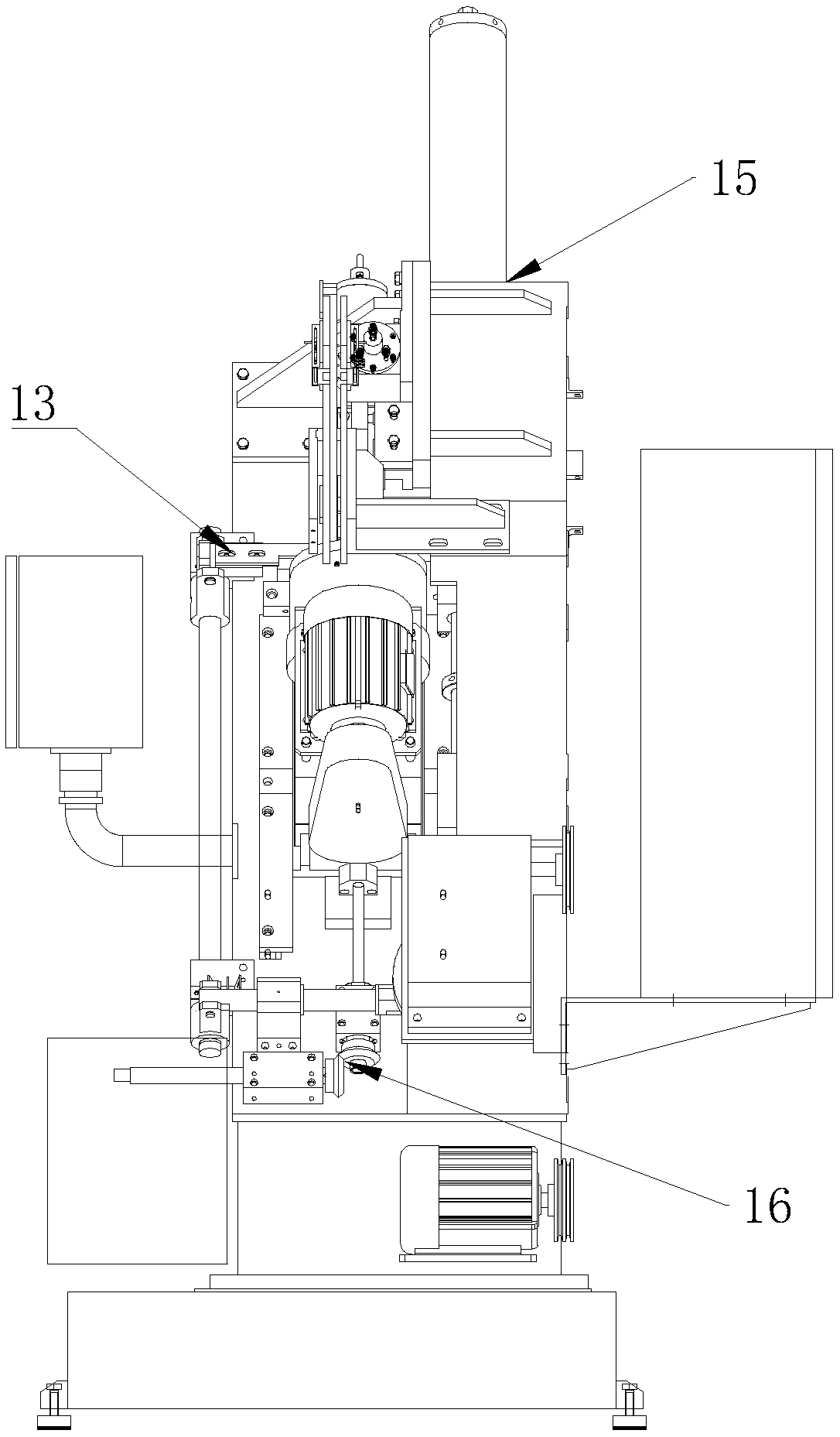
[0014] Such as figure 1 As shown, a cam-type high-speed front end processing machine includes a base 1, on which is provided an inclined bed 2, and the inclined bed 2 is provided with a feeding mechanism, a clamping mechanism, a sliding head and A discharging mechanism, the feeding mechanism includes a feeding plate 3, the clamping mechanism includes a clamping block 5 disposed toward the feeding plate 3, and the head includes a first motor 6 and a power head 7 connected to the first motor 6, The power head 7 is connected with a cutting tool, the base 1 is provided with a second motor 8, and the inclined bed 2 is provided with a reducer 9, and the second motor 8 drives the reducer through a timing belt and a timing wheel 9 rotates, the speed reducer 9 is connected with a feed cam 10 and a feed cam 11, the feed cam 10 is connected with a guide wheel 12, the guide wheel 12 is connected with the clamping block 5, and the feed cam 11 is connected with a push For the material rod 13, the base 1 is also provided with a power lifting mechanism 14 capable of driving the head to slide on the inclined bed 2.
[0015] The cam-type high-speed front-end processing machine of the present invention, the working process is that the workpiece enters the chuck that is the clamping mechanism from the feeding mechanism, the cutter head on the machine head keeps high-speed rotation, the chuck moves forward after clamping the workpiece, and the clamping The head is elongated and driven by the guide wheel 12. After the processing is completed, the chuck is retracted and released. The next product is fed forward, and the finished product is pushed into the discharge slot to complete the processing of a product. It takes only 3 seconds to complete this cycle , When changing products, you can directly use the touch screen and simple mechanical operations and complete the front and back movement of the head. In terms of electrical appliances, it can monitor a part of the wearing parts, and can display the operating status of the machine on the touch screen, can set a variety of product parameters in advance, can switch different parameters between different products, and the spindle position. Compared with the existing technology, the advantage of this solution is that it can increase product output and reduce the number of machines under the same output; reduce manpower, realize multiple machines for one person, and improve work efficiency. It is effective from about one in 15 seconds before to one in 3 seconds; effective Reduce the labor intensity of workers and reduce potential safety hazards.
[0016] Preferably, the inclined bed 2 is provided with a buffer spring and a spring return bucket 15 for protecting the spring.
[0017] Preferably, the feeding plate 3 is provided with a feeding pressing plate 4. The feeding platen 4 can prevent the product from sliding down and ejecting due to too much inertia.
[0018] Preferably, the power lifting mechanism 14 includes a motor, a synchronous wheel, a synchronous belt, and a pair of meshing bevel gear sets 16, one end of which is connected to the synchronous wheel and the other end is connected to the machine head. The power lifting mechanism 14 can adjust the head up and down.
[0019] Preferably, the discharging mechanism includes a discharging plate 17 and a discharging conveyor 18 connected to the discharging plate 17.
[0020] The above are only the preferred embodiments of the present invention, and the protection scope of the present invention is not limited to the above-mentioned embodiments. All technical solutions under the idea of ​​the present invention belong to the protection scope of the present invention. It should be pointed out that for those of ordinary skill in the art, several improvements and modifications made without departing from the principles of the present invention should also be regarded as the protection scope of the present invention.

PUM

no PUM

Description & Claims & Application Information

We can also present the details of the Description, Claims and Application information to help users get a comprehensive understanding of the technical details of the patent, such as background art, summary of invention, brief description of drawings, description of embodiments, and other original content. On the other hand, users can also determine the specific scope of protection of the technology through the list of claims; as well as understand the changes in the life cycle of the technology with the presentation of the patent timeline. Login to view more.

Similar technology patents

Lithographic machine platform and applications thereof

InactiveUS20100233437A1increase product yieldreduce fabrication cost
Owner:NAT APPLIED RES LAB

Method for manufacturing high-silicon composite electrical steel narrow-band product

InactiveCN107626927AIncrease product yieldeasy to operate
Owner:ANGANG STEEL CO LTD

Disc drawing round pipe mold capable of being used by joint

PendingCN113578994AIncrease product yield
Owner:JIANGSU ASIA PACIFIC LIGHT ALLOY TECH CO LTD

Classification and recommendation of technical efficacy words

  • Reduce the number of machines
  • Increase product yield

Automatic detection device for payment process of fee control electric meter

PendingCN111751779AReduce testing costsReduce the number of machines
Owner:HANGZHOU DC ENERGY EQUIP

Organic electro-luminescence display device and method for fabricating the same

ActiveUS20070132374A1increase product yieldreduce defect rate
Owner:LG DISPLAY CO LTD

Light emitting diode package structure

InactiveUS20050012108A1increase product yielddecrease production cost
Owner:LIN MING DER +2

Method of purifying air

ActiveUS20120011887A1increase product yieldexcellent reproduction
Owner:TAIYO NIPPON SANSO CORP

Semiconductor memory device and method of operating the same

ActiveUS20150135040A1increase product yield
Owner:SK HYNIX INC
Why Eureka
Try Eureka