An emergency brake control system for preventing side slip of a vehicle

An emergency braking and control system technology, applied in electric braking systems, brakes, electric vehicles, etc., can solve problems such as unavoidable accidents, driving safety hazards, locked vehicles, etc., to improve stability and safety, improve Recycling efficiency and the effect of reducing the risk of sideslip

Inactive Publication Date: 2018-11-27
杜永波
View PDF4 Cites 5 Cited by
  • Summary
  • Abstract
  • Description
  • Claims
  • Application Information

AI Technical Summary

Problems solved by technology

However, since these auxiliary braking devices do not have intelligent control functions, they do not consider the impact of the braking force on the driving state of the vehicle during the braking process, resulting in the vehicle overturning due to excessive braking force, or due to braking. The power is too small to stop the car within a safe distance, which will still cause traffic accidents and bring new safety hazards to driving
[0005] In addition, when the vehicle is in an emergency, when the traditional mechanical brake device (hand brake and foot brake) is used to brake, because it only applies a large braking force to the rear two wheels, even if the ABS anti-lock braking system is installed, it will The phenomenon of vehicle tailing due to rear wheel locking is a great potential safety hazard; the key factor lies in the shortcomings of the ABS system itself, which is a passive braking system that cannot actively identify the presence of vehicles in advance Potential safety hazards, often when the driver is aware of the existence of danger, it is difficult to avoid accidents

Method used


Image

  • An emergency brake control system for preventing side slip of a vehicle
  • An emergency brake control system for preventing side slip of a vehicle
  • An emergency brake control system for preventing side slip of a vehicle

Examples


Embodiment Construction

[0045] An emergency brake control system for preventing vehicle skidding according to the present invention will be described in detail below in conjunction with the accompanying drawings and embodiments.

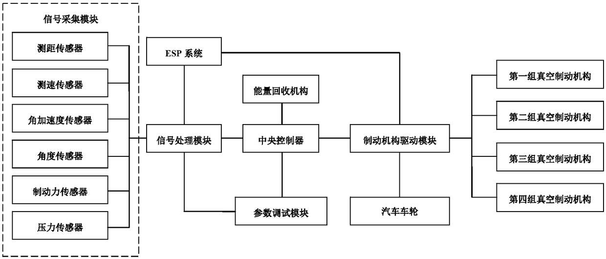
[0046] Such as figure 1 As shown, the present invention provides an auxiliary braking system for preventing vehicle sideslip, the system specifically includes: a signal acquisition module, a signal processing module, a central controller, a braking mechanism driving module, at least two groups of vacuum braking mechanisms, ESP system and energy recovery mechanism.

[0047] The signal acquisition module is used to collect the driving state signal and the braking force signal of the automobile;

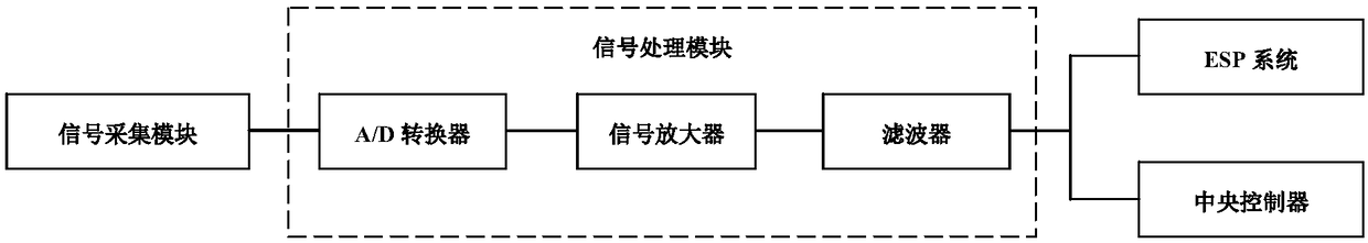
[0048] The signal processing module is used to process the driving state signal and the braking force signal to generate a signal for identification by the ESP system and the central controller;

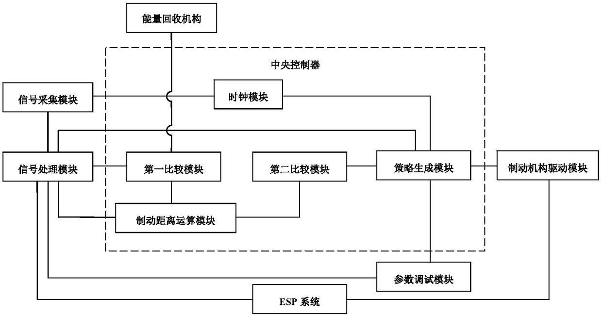
[0049] The central controller judges whether the car is in an emergency braking state...


PUM


Abstract

The invention provides an emergency braking control system for preventing the side slip of an automobile, which comprises a signal acquisition module, a signal processing module, a central controller,a braking mechanism driving module, at least two groups of vacuum braking mechanisms, an ESP system and an energy recovery mechanism. The system can monitor the moving state of the running vehicle inreal time, Vacuum braking strategy matched with the current state of the automobile is generated by signal analysis, which can cooperate with the main braking system of the automobile, and the auxiliary braking operation is carried out through the intelligent control mechanism, the braking distance is significantly reduced, and the stability and safety of the service braking are effectively improved; The invention also integrates the ESP into the system, so that the vehicle can maintain optimal stability under various conditions, and the risk of side slip of the vehicle is reduced in the caseof over-steering or over-braking. Energy recovery mechanisms are also provided to recover excess energy released by the vehicle during braking or inertial taxiing, which contributes to energy conservation and environmental protection.

Description

technical field [0001] The invention relates to the technical field of automobile braking, in particular to an emergency braking control system for preventing automobile sideslip. Background technique [0002] In recent years, as the number of domestic automobiles has increased year by year, road traffic safety has become more and more severe. According to the research, in many traffic accidents, rear-end collisions account for more than 70% of the total accident rate, especially on expressways, which cause more rear-end collisions, causing more serious losses of personnel and property. The rear-end collision accidents are mostly caused by the rear car running at high speed unable to stop the car in a short distance when the front car is braking in an emergency. [0003] At present, the existing automobiles are all equipped with an ABS system, the purpose of which is to prevent the wheels from locking up under emergency braking conditions, so as to ensure that the adhesion ...

Claims


Application Information

Patent Timeline
IPC IPC(8): B60T1/14B60T7/12B60L7/18
CPCB60L7/18B60T1/14B60T7/12
Inventor 栗红允栗志
Owner 杜永波
Why Eureka
Try Eureka