Permanent-magnet speed-adjustable motor and control method thereof

A permanent magnet speed regulation and motor side technology, applied in the direction of permanent magnet clutch/brake, control system, control electromechanical brake, etc., can solve the problems of poor control response speed and corresponding precision, high working temperature, slow speed, etc., to achieve Improved reliability and safety, faster control response, and improved reliability

Pending Publication Date: 2018-11-27
NANJING MAGNET INTELLIGENCE TECH CO LTD
View PDF0 Cites 1 Cited by
  • Summary
  • Abstract
  • Description
  • Claims
  • Application Information

AI Technical Summary

Problems solved by technology

The speed-regulating permanent magnetic coupler is essentially a slip speed regulation, and its efficiency is positively correlated with the output speed. When the output speed is low, the efficiency is very low. For example, the output speed of the speed-regulating permanent magnetic coupler is 50% of the rated speed. When the speed is high, its working efficiency is only 48%
[0004] 2. The working temperature of the speed-regulating permanent magnetic coupler is high
Since the slip power loss of the speed-regulating permanent magnetic coupler is all converted into heat, the operating temperature of the equipment is high when it works at low speed.
[0005] 3. The reliability of the speed regulating mechanism is not high
The main structure of the speed-regulating permanent magnetic coupler has high reliability, but its speed-regulating mechanism uses mechanical position adjustment to achieve the purpose of speed-regulating, and the speed-regulating mechanism realizes position adjustment under high-speed conditions with low reliability
[0006] 4. Poor control response speed and corresponding precision
Since the speed-regulating permanent magnet coupler realizes speed regulation through the adjustment of the mechanical structure driven by the action of the electric actuator, its corresponding speed is slow and the response accuracy is low.

Method used


Image

  • Permanent-magnet speed-adjustable motor and control method thereof
  • Permanent-magnet speed-adjustable motor and control method thereof
  • Permanent-magnet speed-adjustable motor and control method thereof

Examples


Embodiment 1

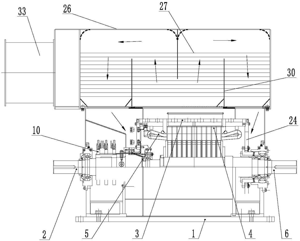
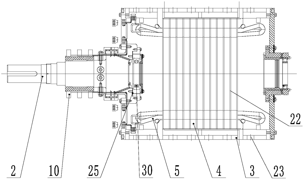
[0036]A permanent magnet speed-regulating motor and a control method thereof provided in this embodiment include a motor base 1, an outer rotor assembly and an inner rotor assembly are respectively provided on the motor base 1 and at both ends along its length direction through bearings, The outer rotor assembly includes a first rotating shaft 2 on which a collector ring 10 is arranged, and a cylindrical iron core holder 3 is arranged on one end of the first rotating shaft 2 inside the motor base 1 , the outer rotor core 4 and multiple sets of induction coils 5 matched with the outer rotor core 4 are arranged in the middle of the iron core holder 3, the output ends of the induction coils 5 are connected to the slip ring 10, and The number of groups of the induction coils 5 is 6 groups, the number of the slip rings 10 is 6, and 3 groups of non-adjacent induction coils 5 form a three-phase potential, and there are 2 three-phase potentials in total;

[0037] The inner rotor assem...

Embodiment 2

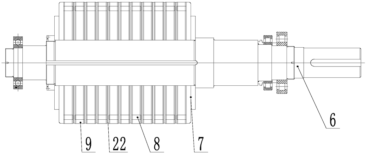
[0054] This embodiment discloses a permanent magnet speed-regulating motor. This technical solution is the same as the technical solution of the embodiment, wherein the number of groups of induction coils 5 is 12, the number of said slip rings 10 is 12, and every three groups of induction The coil 5 forms a three-phase potential, and there are 4 three-phase potentials in total, and the radial unilateral gap between the permanent magnet 9 and the outer rotor core 4 is 4mm, and the θ is 20°, wherein the circuit selection switch 11 and the implementation The technical solutions in Example 1 are similar and can be directly obtained by analogy;

[0055] The control method of the permanent magnet speed regulating motor is carried out in the following steps:

[0056] Step 1: Control the circuit selection switch 11 through the main controller 17, first connect the four three-phase potentials in parallel and then connect them in series with the motor side filter 12, then turn on the is...

Embodiment 3

[0061] This embodiment discloses a permanent magnet speed-regulating motor. This technical solution is the same as that of the embodiment, wherein the number of induction coils 5 is 18, and the number of collector rings 10 is 18. Every three groups of induction The coil 5 forms a three-phase potential, and there are 6 three-phase potentials in total, and the radial unilateral gap between the permanent magnet 9 and the outer rotor core 4 is 5mm, and the θ is 30°, wherein the circuit selection switch 11 and the implementation The technical solutions in Example 1 are similar and can be directly obtained by analogy;

[0062] The control method of the permanent magnet speed regulating motor is carried out in the following steps:

[0063] Step 1: Control the circuit selection switch 11 through the main controller 17, first connect the six three-phase potentials in parallel and then connect them in series with the motor side filter 12, then turn on the isolating switch 16, and connec...


PUM


Abstract

The invention discloses a permanent-magnet speed-adjustable motor which comprises a motor base, wherein an outer rotor assembly and an inner rotor assembly are respectively arranged on the motor baseand at the two ends in the length direction of the motor base through bearings; the outer rotor assembly comprises a first rotating shaft, collecting rings are arranged on the first rotating shaft, abarrel-shaped iron core retainer is arranged at one end in the motor base of the first rotating shaft, an outer rotor iron core and a plurality of induction coils matched with the outer rotor iron cores are arranged in the iron core retainer, the output ends of the induction coils are connected with the collecting rings, the group number of the induction coils is 3N (the N is an integer), the group number of the induction coils is larger than or equal to 6, the number of the collecting rings is 3N, every three groups of induction coils can form a three-phase potential, and N three-phase potentials with the completely same phases can be achieved.

Description

technical field [0001] The invention relates to a permanent magnet speed regulating motor, in particular to a permanent magnet speed regulating motor and a control method thereof. Background technique [0002] The speed-regulating permanent magnetic coupler is more and more recognized by the industry, but in actual use, the speed-regulating permanent magnetic coupler also exposes some problems, mainly including: [0003] 1. The efficiency of the speed-regulating permanent magnetic coupler is low. The speed-regulating permanent magnetic coupler is essentially a slip speed regulation, and its efficiency is positively correlated with the output speed. When the output speed is low, the efficiency is very low. For example, the output speed of the speed-regulating permanent magnetic coupler is 50% of the rated speed. When the speed is high, its working efficiency is only 48%. [0004] 2. The working temperature of the speed-regulating permanent magnetic coupler is high. Since t...

Claims


Application Information

Patent Timeline
Patent Type & Authority Applications(China)
IPC IPC(8): H02K49/10H02P15/00H02J3/38
CPCH02K49/106H02J3/381H02P15/00
Inventor 黄忠念田德建吴勇韩立彪
Owner NANJING MAGNET INTELLIGENCE TECH CO LTD
Why Eureka
Try Eureka