Water treatment separation device

A separation equipment and water treatment technology, which is applied in the direction of filtration separation, separation method, mobile filter element filter, etc., can solve the problems of settlement pollution of lower clear water, low efficiency of floc impurity separation, inconvenient water treatment efficiency, etc., to achieve floc Effects of low concentration, reduced probability, and ease of separation

Inactive Publication Date: 2018-11-30
湖州市腾跃环保科技有限公司
View PDF7 Cites 0 Cited by
  • Summary
  • Abstract
  • Description
  • Claims
  • Application Information

AI Technical Summary

Problems solved by technology

[0002] Water treatment methods include physical treatment and chemical treatment. Human beings have used water treatment methods for many years. Physical methods include the use of various filter materials with different pore sizes, and the use of adsorption or barrier methods to exclude impurities in water. Adsorption The more important method is to use activated carbon for adsorption. The barrier method is to pass water through the filter material, so that the larger impurities cannot pass through, and then obtain cleaner water. In addition, the physical method also includes the precipitation method, which is to make the specific gravity relatively Small impurities are floated on the water surface and taken out, or impurities with a large specific gravity are deposited below, and then obtained. When water treatment uses chemical methods to separate dirt and impurities, it is necessary to produce flocs through the coagulation of drugs and impurities, and then dissolve them in water. The fine floating air bubbles in the air drive the flocs to float on the water surface, and then the floc sludge on the water surface is scraped away by the mechanical mud scraper, so as to achieve a certain degree of mud-water separation. Some existing separation equipment does not perform due to floating The flocs accumulate more and more. Under the mechanical action of the mud scraper, it is easy to settle and pollute the lower clear water. At the same time, this separation method has low separation efficiency for floc impurities, which is not convenient for improving water treatment efficiency.

Method used


Image

  • Water treatment separation device
  • Water treatment separation device
  • Water treatment separation device

Examples


Embodiment 1

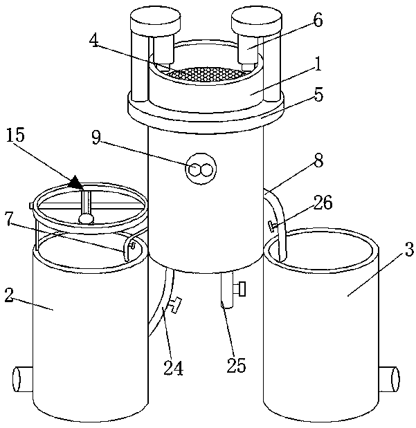
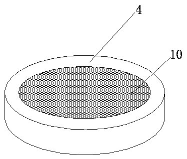
[0030] refer to Figure 1-2 , a water treatment separation equipment, including the first cylinder 1, the second cylinder 2 and the third cylinder 3, and the first cylinder 1, the second cylinder 2 and the third cylinder 3 are in the shape of "pin" Type arrangement, the inner wall of the first cylinder 1 is connected with the first piston 4, the middle part of the first piston 4 is provided with an opening, the inner wall of the opening and the inner wall of the third cylinder 3 are connected with a filter screen 10, the first cylinder 1 The outer wall is sleeved with a fixed ring 5, and the fixed ring 5 is connected with an electric push rod 6 through a pole, and the telescopic end of the electric push rod 6 is connected with the first piston 4, and the outer wall of the first cylinder 1 is connected with a first outlet. The water pipe 7 and the second water outlet pipe 8, and the first water outlet pipe 7 and the second water outlet pipe 8 are arranged above the second cylin...

Embodiment 2

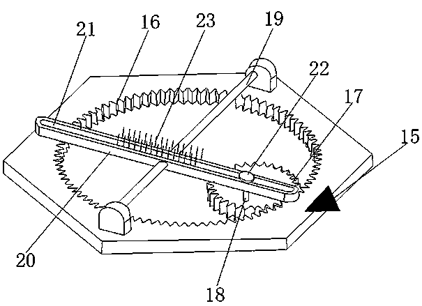
[0032] refer to Figure 1-3 , a water treatment separation device, which is basically the same as that of Embodiment 1, the difference is that the tops of the first cylinder 1 and the second cylinder 2 are connected with a separation assembly 15 through a bracket, and the separation assembly 15 includes a ring gear bar 16 , the ring gear bar 16 is connected with a drive gear 17, and the drive gear 17 is meshed with the ring gear bar 16, the drive gear 17 is connected with a traction shaft 18 near the outer wall of the second cylinder 2, and the traction shaft 18 is arranged on the drive At the edge of the bottom outer wall of the gear 17, the bottom of the ring gear bar 16 is connected with a fixed rod 19 through a support frame, and a reciprocating adjustment plate 20 is also provided under the ring gear bar 16, and the reciprocating adjustment plate 20 is inserted on the fixed rod 19, A chute 21 is opened on the reciprocating adjustment plate 20 , and the traction shaft 18 p...

Embodiment 3

[0034] refer to Figure 1-5 , a kind of water treatment and separation equipment, which is basically the same as that of Embodiment 1, the difference is that the specific material of the first cylinder 1, the second cylinder 2 and the third cylinder 3 is transparent glass, which is convenient for observation, and the first cylinder The bottom of the body 1 is connected with an air outlet pipe 24 and an air return pipe 25, and the end of the air outlet pipe 24 away from the first cylinder body 1 is connected with the second cylinder body 2, and the air outlet pipe 24 and the air return pipe 25 are connected with electromagnetic valves 26. A telescopic rod 11 is connected to the inner wall of the bottom of a cylinder 1, and the outer wall of the telescopic rod 11 is provided with a reset spring 12. The end of the telescopic rod 11 away from the bottom wall of the first cylinder 1 is connected to a second piston 13, and the first cylinder 1 The inner wall of the inner wall is als...


PUM


Abstract

The invention discloses a water treatment separation device and belongs to the technical field of water treatment equipment. The water treatment separation device comprises a first cylinder, a secondcylinder and a third cylinder. The first cylinder, the second cylinder and the third cylinder are arranged in a Chinese character Pin shape. A first piston is connected to the inner wall of the firstcylinder. The outer wall of the first cylinder is sleeved by a fixed ring. The fixed ring is connected to an electric push rod through a support rod. The telescopic end of the electric push rod is connected to the first piston. The outer wall of the first cylinder is connected to a first water outlet pipe and a second water outlet pipe. The first water outlet pipe and the second water outlet pipeare respectively arranged above the second cylinder and the third cylinder. The first water outlet pipe and the second water outlet pipe are connected to the outer wall of the first cylinder. The first water outlet pipe and the second water outlet pipe are respectively disposed above the second cylinder body and the third cylinder body. The outer wall of the first cylinder is connected to a control switch. The device has a simple structure, realizes filtering separation of water to be treated, treats water in different layers, separates water containing floc impurities through a mechanical scraper plate and improves the separation efficiency of floc impurities in the water treatment process.

Description

technical field [0001] The invention relates to the technical field of water treatment equipment, in particular to a water treatment and separation equipment. Background technique [0002] Water treatment methods include physical treatment and chemical treatment. Human beings have used water treatment methods for many years. Physical methods include the use of various filter materials with different pore sizes, and the use of adsorption or barrier methods to exclude impurities in water. Adsorption The more important method is to use activated carbon for adsorption. The barrier method is to pass water through the filter material, so that the larger impurities cannot pass through, and then obtain cleaner water. In addition, the physical method also includes the precipitation method, which is to make the specific gravity relatively Small impurities are floated on the water surface and taken out, or impurities with a large specific gravity are deposited below, and then obtained....

Claims


Application Information

Patent Timeline
Patent Type & Authority Applications(China)
IPC IPC(8): B01D33/01B01D33/74B01D33/76
CPCB01D33/0183B01D33/74B01D33/76
Inventor 沈越
Owner 湖州市腾跃环保科技有限公司
Why Eureka
Try Eureka