
Metal plate transverse cutting production line

A metal sheet and production line technology, applied in metal processing equipment, metal processing machinery parts, shearing devices, etc., can solve the problems of affecting the cutting quality, difficult to adjust the cutting direction, harm to workers, etc., to avoid inhaling a large amount of dust, reduce Small buffer force, the effect of increasing cutting quality

Inactive Publication Date: 2018-11-30
广州宝升新型材料有限公司
View PDF5 Cites 3 Cited by
  • Summary
  • Abstract
  • Description
  • Claims
  • Application Information

AI Technical Summary

Problems solved by technology

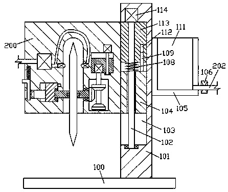
[0002] In the sheet metal cross-cutting production and processing system, the cutting of sheet metal is essential. At present, the cutting equipment for sheet metal tends to generate a lot of dust during cutting, which affects the cutting quality and causes a lot of harm to the staff. Moreover, the current Cutting equipment is difficult to adjust in the cutting direction, therefore, needs improvement

Method used


Image

  • Metal plate transverse cutting production line
  • Metal plate transverse cutting production line
  • Metal plate transverse cutting production line

Examples


Embodiment Construction

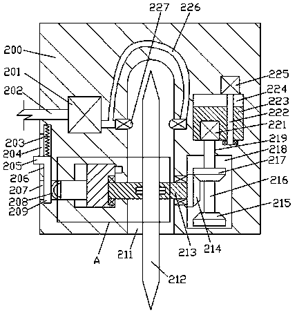
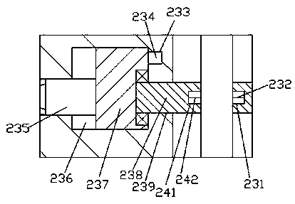
[0012] Combine below Figure 1-3 The present invention will be described in detail.

[0013] Reference Figure 1-3 According to an embodiment of the present invention, a sheet metal cross-cutting production line includes a bottom plate 100 and a support seat 101 fixedly mounted on the bottom plate 100, and a first sliding cavity 103 is provided in the left end surface of the support seat 101, A first sliding block 113 and a buffer block 104 are respectively installed in the first sliding cavity 103 in a sliding fit, and a first threaded rod 102 is installed in the internal thread of the sliding block 113. A first motor 114 is installed in cooperation, the first motor 114 is fixed in the top wall of the first sliding cavity 103, and the bottom extension end of the first threaded rod 102 rotates with the bottom wall of the first sliding cavity 103 The buffer block 104 is in clearance fit with the first threaded rod 102, a buffer spring 108 is fixedly installed between the top sur...


PUM


Abstract

The invention discloses a metal plate transverse cutting production line. The production line comprises a bottom plate and a supporting base fixedly arranged on the bottom plate. The left end face ofthe supporting base is internally provided with a first sliding cavity, a first sliding block and a buffer block are arranged in the first sliding cavity separately through sliding fit, and a first threaded rod is arranged in the sliding block through threaded fit. A first motor is arranged at the extending tail end of the top of the first threaded rod through power matching, the first motor is fixedly arranged in the top wall of the first sliding cavity, and the extending tail end of the bottom of the first threaded rod is in rotating fit connection with the bottom wall of the first sliding cavity. The buffer block is in clearance fit with the first threaded rod, and a buffer spring is fixedly arranged between the top end face of the buffer block and the bottom end face of the first sliding block. A guide sliding cavity is formed in the end face of the top of the first sliding block, and a guide sliding block is arranged in the guide sliding cavity through sliding fit.

Description

Technical field [0001] The invention relates to the technical field of sheet metal processing, in particular to a metal sheet cross-cutting production line. Background technique [0002] In the sheet metal cross-cutting production and processing system, the cutting process of the sheet metal is indispensable. At present, the cutting equipment for sheet metal is prone to generate a large amount of dust during cutting, which affects the cutting quality and causes a lot of harm to the staff. Moreover, the current The cutting equipment is difficult to adjust in the cutting direction, therefore, it needs improvement. Summary of the invention [0003] The purpose of the present invention is to provide a metal sheet cross-cutting production line, which is used to overcome the above-mentioned defects in the prior art. [0004] A sheet metal cross-cutting production line according to the present invention includes a bottom plate and a support seat fixedly installed on the bottom plate. A fi...

Claims


Application Information

Patent Timeline
Patent Type & Authority Applications(China)
IPC IPC(8): B23D19/00B23Q11/00B23D36/00
CPCB23D19/00B23D36/0008B23Q11/0042
Inventor 徐锦杰
Owner 广州宝升新型材料有限公司
Learn More