Production process of thermal insulation wall plate for light fireproof building exterior wall

A technology for fire-resistant buildings and thermal insulation wall panels, which is applied in the field of thermal insulation materials for external walls of buildings, and can solve problems such as poor fixed strength of thermal insulation materials, substandard thermal insulation indicators, and short service life, and achieve good flame-resistant and fire-resistant effects, reducing Effect of weight, increasing strength properties

Pending Publication Date: 2018-11-30
洛阳佳联建材有限公司
View PDF7 Cites 0 Cited by
  • Summary
  • Abstract
  • Description
  • Claims
  • Application Information

AI Technical Summary

Problems solved by technology

At present, the existing building insulation methods mainly include the technology of adding thin mortar coating to the insulation layer. This method is to directly fix the insulation materials such as extruded plastic board and expanded polystyrene board on the building wall after the construction is completed. , and then use cement mortar to smear the surface, and finally complete the wall insulation of the building. The existing wall insulation technology requires secondary construction, poor fixing strength of the insulation material, easy to fall off, short service life, poor fire resistance, Insufficient heat preservation indicators and other disadvantages

Method used


Image

  • Production process of thermal insulation wall plate for light fireproof building exterior wall

Examples


Embodiment 1

[0028] Production of thermal insulation wall panels for lightweight fireproof building exterior walls with dimensions of length 2440×width 600×thickness 100mm:

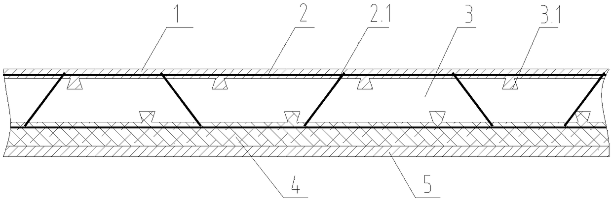
[0029]First place the insulation layer 3 between a pair of truss-type steel wire mesh frames 2 parallel to each other, and evenly distribute steel mesh oblique bars 2.1 between a pair of mutually parallel truss-type steel wire mesh frames 2, and steel mesh oblique insertion bars 2.1 make A pair of parallel truss-type steel wire mesh frames 2 and the insulation layer 3 between them are connected as a whole, and the protective connection layer 1 is laid in a mold with the required size of the external wall insulation wall panel, and it is smoothed according to the set height. Before the protective connection layer 1 is dehydrated and solidified, press a pair of parallel truss-type steel wire mesh frame 2 with the insulation layer 3 into the protection connection layer 1, so that the lower surface of the protection connec...


PUM

PropertyMeasurementUnit
lengthaaaaaaaaaa
widthaaaaaaaaaa
thicknessaaaaaaaaaa

Abstract

Disclosed is a production process of a thermal insulation wall plate for a light fireproof building exterior wall. Firstly, a thermal insulation layer is placed between a pair of parallel truss-type steel wire mesh frames, steel mesh slant ribs are evenly distributed between the pair of parallel truss-type steel wire mesh frames, and the pair of parallel truss-type steel wire mesh frames with thethermal insulation layer are pressed into a protective connecting layer to ensure that the lower surface of the protective connecting layer expands into the gap between the thermal insulation layer and the truss-type steel wire mesh frame on the upper surface of the thermal insulation layer and into a thermal insulation layer groove in the upper surface of the thermal insulation layer. A fireprooflayer is evenly coated on the lower surface of the thermal insulation layer to ensure that the upper surface of the fireproof layer expands into the gap between the thermal insulation layer and the truss-type steel wire mesh frame on the lower upper surface of the thermal insulation layer and into a thermal insulation layer groove in the lower surface of the thermal insulation layer. Finally, a reinforcing layer is coated on the lower surface of the fireproof layer and is separated from a forming mold after dewatering and forming. The fireproofing effect and heat preservation effect are good.Due to the truss-type steel wire mesh frames, the pull-out resistance between all layers is guaranteed, and the strength performance of the wall plate is improved.

Description

technical field [0001] The invention relates to a thermal insulation material for the outer wall of a building, in particular to a production process of a light-weight thermal insulation wall panel for the outer wall of a fireproof building. Background technique [0002] Recently, incidents of building exterior wall insulation materials falling off and catching fire continue to occur. The disadvantages of the use of traditional building wall insulation materials have gradually become prominent. In addition, the country has higher and higher requirements for building energy-saving indicators, and the fire performance of building insulation materials needs to be strictly controlled. Under the requirements of national policies, new thermal insulation and energy-saving materials are bound to undergo a major technological update. At present, the existing building insulation methods mainly include the technology of adding thin mortar coating to the insulation layer. This method is...

Claims


Application Information

Patent Timeline
Patent Type & Authority Applications(China)
IPC IPC(8): B28B19/00
CPCB28B19/0015
Inventor 焦永乐李波梁峰梁景乐
Owner 洛阳佳联建材有限公司
Why Eureka
Try Eureka