
Energy-saving variable frequency artificial wetland water treatment system

A technology for water treatment systems and constructed wetlands, applied in biological water/sewage treatment, water/sludge/sewage treatment, chemical instruments and methods, etc., can solve unfavorable and stable treatment and ensure the quality of effluent water, and large fluctuations in the treatment load of constructed wetlands , large fluctuations in water flow velocity, etc., to achieve good power saving effects, convenient later maintenance, and high-efficiency operation

Pending Publication Date: 2018-11-30
BEIJING ORIENT LANDSCAPE
View PDF3 Cites 1 Cited by
  • Summary
  • Abstract
  • Description
  • Claims
  • Application Information

AI Technical Summary

Problems solved by technology

[0005] In order to ensure stable effluent water quality, you can consider adjusting the flow rate to ensure the hydraulic retention time, but what affects the flow rate is the lift pump placed at the entrance of the constructed wetland. The lift pump has only one working current and frequency, which cannot be changed in practical applications. In actual use, most of them adopt relatively extensive switch control, which cannot dynamically adjust the water flow rate in the wetland according to the water quality of the effluent, resulting in large fluctuations in the flow rate of the water flow in the wetland, and large fluctuations in the processing load of the constructed wetland, which is not conducive to stable treatment and guarantee of water quality. and may consume more power

Method used


Image

  • Energy-saving variable frequency artificial wetland water treatment system
  • Energy-saving variable frequency artificial wetland water treatment system
  • Energy-saving variable frequency artificial wetland water treatment system

Examples


Embodiment Construction

[0021] The technical solutions of the present invention will be described in further detail below with reference to the accompanying drawings and embodiments.

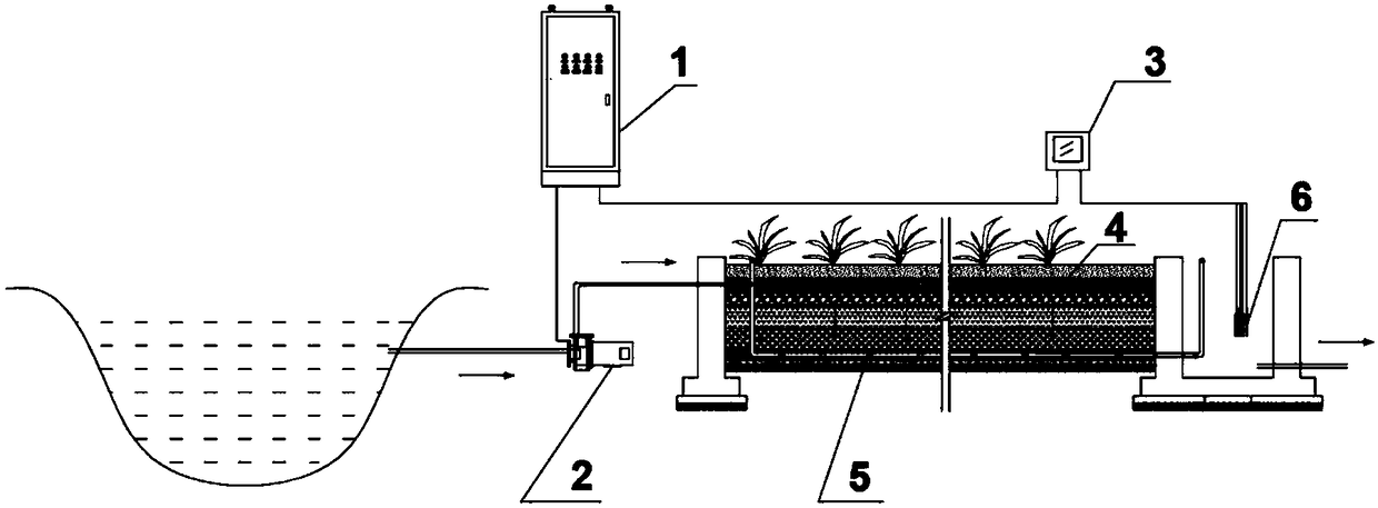
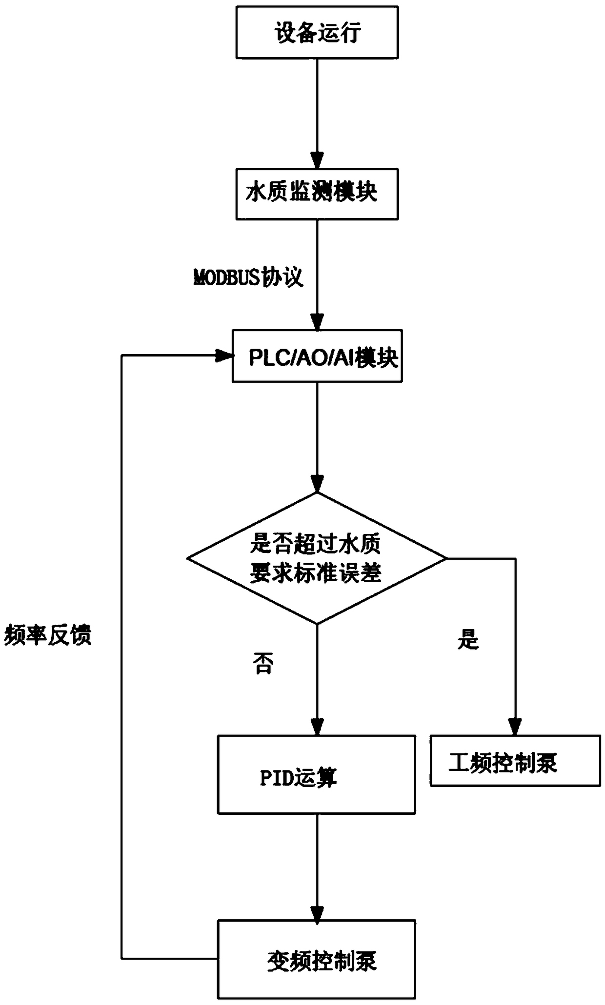
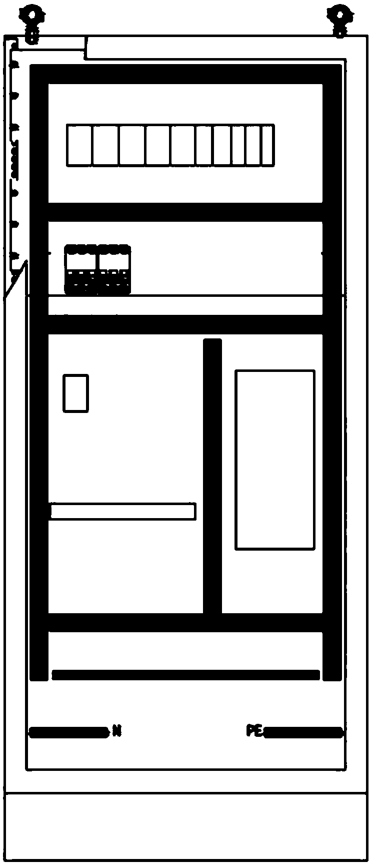
[0022] The invention provides an energy-saving frequency conversion artificial wetland water treatment system, such as Figure 1 ~ Figure 3 As shown, a preferred embodiment of the present invention is shown therein. like figure 1 As shown, the energy-saving frequency conversion constructed wetland water treatment system includes a constructed wetland main body, a surface water area, and a lift pump 2 arranged between the surface water area and the constructed wetland main body. It is characterized in that: the water outlet of the lift pump 2 is connected to The water distribution pipe 4 in the main body of the constructed wetland is connected, and the water outlet position of the water collection pipe 5 in the main body of the constructed wetland is provided with a water quality monitoring sensor 6, and the water qual...


PUM


Abstract

The invention relates to an energy-saving variable frequency artificial wetland water treatment system, which comprises an artificial wetland main body, an earth surface water area and a lifting pumparranged between the earth surface water area and the artificial wetland main body, wherein the water outlet end of the lifting pump is connected to the water distribution pipe in the artificial wetland main body, the water outlet position of the water collection pipe in the artificial wetland main body is provided with a water quality monitoring sensor, the water quality monitoring sensor is electrically connected to a water quality monitoring unit, the artificial wetland water treatment system further comprises a control unit, and the control unit acquires the water quality data of the wateroutlet in the water quality monitoring unit and controls the operating frequency of the lifting pump in a variable frequency manner according to the water quality data. According to the present invention, the structural design of the energy-saving variable frequency artificial wetland water treatment system is simple and reasonable; and by adopting the variable frequency control technology, the on-demand operation of the lifting pump is achieved, the daily processing capacity of the wetland is increased, and the long-term safe and efficient operation of the wetland is ensured.

Description

technical field [0001] The invention relates to the field of sewage treatment, in particular to an energy-saving frequency conversion artificial wetland water treatment system. Background technique [0002] Constructed wetland is a kind of structure constructed by using engineering means to simulate natural wetland system for sewage treatment, which has the characteristics of high efficiency and low consumption. Since the 1970s, this technology has been widely used in the treatment of various wastewater, especially in the treatment of rural domestic sewage. [0003] For the effluent quality of constructed wetlands, factors affecting the treatment effect of constructed wetlands include hydraulic load (HLR), hydraulic retention time (HRT), climate, raw water quality, plants, and ambient temperature. According to the current status of the existing constructed wetland technology, the decontamination efficiency of the wetland is only 32% of its function, and the main limiting fa...

Claims


Application Information

Patent Timeline
IPC IPC(8): C02F3/32
CPCC02F3/32
Inventor 赵彦松马俊杰刘硕
Owner BEIJING ORIENT LANDSCAPE
Learn More