Lamp, vehicle with lamp and vehicular lamp demisting method

A lamp body and lamp technology, which is applied to road vehicles, vehicle parts, motor vehicles, etc., can solve the problems of space occupation in the lamp, difficulty in air circulation in the lamp, dehumidification speed and effect need to be improved, and achieve an effective dehumidification method Effect

Inactive Publication Date: 2018-11-30
JIAXING HELLA LIGHTING CO LTD
View PDF6 Cites 15 Cited by
  • Summary
  • Abstract
  • Description
  • Claims
  • Application Information

AI Technical Summary

Problems solved by technology

However, with the rapid development of car lamp technology, the internal structure design of car lamps is becoming more and more complex, and the space inside the lamp is occupied by more and more decorative parts and electronic components, making the air circulation in the lamp difficult.
Conventional breathable caps or breathable membranes can no longer discharge the fog inside the lamp in time, so the water vapor condenses on the inner mask of the lamp to cause sagg

Method used


Image

  • Lamp, vehicle with lamp and vehicular lamp demisting method
  • Lamp, vehicle with lamp and vehicular lamp demisting method
  • Lamp, vehicle with lamp and vehicular lamp demisting method

Examples


Embodiment 1

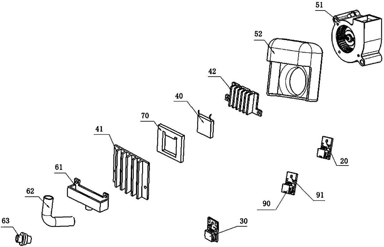
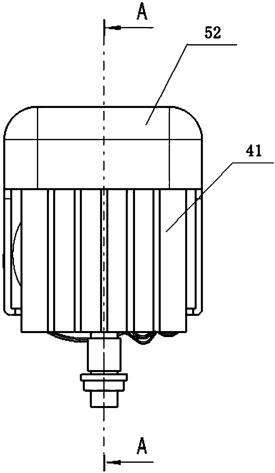
[0072] Refer to Figure 2-4 In this embodiment, the semiconductor condensing module 40 is arranged in the ventilation duct 52. Specifically, the semiconductor condensing module 40 is fixed with respect to the air outlet direction of the fan 51, the cold end and the cold end heat sink 42 in the semiconductor condensing module 40 face the fan 51, and the hot end and the hot end heat sink 41 face away from the fan 51. Such as Figure 4 As shown, the dotted line points to the air flow direction. After the fan 51 is started, the air in the housing 10 is drawn into the fan 51 through the air inlet by the fan 51 for cooling. The air from the fan 51 is first sent to the semiconductor condensing module 40 through the ventilation duct 52 until the cold end and the cold end dissipate heat. The heat of the cold end fin 42 is taken away by the blowing air. The cold end condenses the water vapor in the wind and forms water droplets out of the shell 10; the remaining air will become dry and l...

Embodiment 2

[0074] Refer to Figure 5-7 The semiconductor condensing module 40 is also arranged in the ventilation duct 52, the hot end and the hot end heat sink 41 are facing the fan 51, and the cold end and the cold end heat sink 42 are facing away from the fan 51. Such as Figure 7 As shown, the dotted line points to the air flow direction. After the fan 51 is started, the air in the housing 10 cooled by the fan 51 first passes through the hot-end heat sink 41, and then cools the hot-end heat sink 41, and then blows the air to the cold end and the cold-end heat sink 42, the cold end and The cold end heat sink 42 condenses the water vapor and discharges water droplets out of the lamp body. As the air passes through the cold end, the temperature of the air will decrease and become dry, making it difficult to generate fog in the lamp.

[0075] The difference between the first embodiment and the second embodiment above is that the order of heat dissipation and dehumidification is reversed. ...

Embodiment 3

[0077] Refer to Figure 8-10 , An opening is provided on the housing 10 of the lamp body, and the hot-end heat sink 41 has an extension part in addition to a plurality of heat dissipation fins. The extension part extends through the opening to the outside of the housing 10, the hot-end heat sink 41 Part 41 is arranged inside the housing 10, and part is arranged outside the housing 10 to dissipate heat through conduction. The cold end and cold end heat sink 42 are attached to the hot end heat sink 41 arranged in the housing 10 to dehumidify the air in the housing 10. The nature of the hot-end heat sink 41 reduces the temperature by itself, which can save costs. It can be understood that, in order to prevent water or dust from infiltrating into the gap between the extension and the opening, a sealing ring 80 may be provided between the extension and the opening to prevent water and dust.

[0078] In the above three embodiments, the drainage module can be configured to include a d...


PUM


Abstract

The invention provides a lamp, which comprises a shell and a dehumidifying system in the shell. The dehumidifying system comprises a sensor monitoring module, a semiconductor condensation module and adrainage module. The sensor monitoring module comprises at least one temperature and humidity sensor and a first control unit and is used for detecting the temperature and humidity in the lamp and sending temperature and humidity information to the semiconductor condensation module. The semiconductor condensation module comprises at least one semiconductor and a second control unit, and each semiconductor comprises a cold end and a hot end. The sensor monitoring module and the semiconductor condensation module are connected through the corresponding first control unit and the second control unit. The drainage module is arranged below each cold end and communicated with an external space of the shell, each cold end refrigerates to enable moisture in the shell to be condensed at the corresponding cold end, and condensed water flows to the drainage module to be discharged out of the shell. The invention further provides a vehicle and a demisting method. Internal automatic demisting of avehicular lamp can be realized, and potential problems of mist and sagging in the lamp are solved.

Description

Technical field [0001] The invention relates to the field of vehicle control, in particular to a lamp body, a vehicle with the lamp body, and a method for defogging the lamp. Background technique [0002] The rapid progress in the field of vehicles makes people put forward higher requirements on all parts of the vehicle. At present, car lights mainly use breathable caps or breathable membranes to achieve air exchange inside and outside the lamp. However, with the rapid development of car lamp technology, the internal structure of the car lamp has become more and more complicated. The space inside the lamp is occupied by more and more decorative parts and electronic components, and the air circulation in the lamp is difficult. Conventional breathable caps or breathable membranes can no longer discharge the fog inside the lamp in time, so the water vapor condenses on the lamp inner mask to cause sag, which ultimately affects the use of the lamp. [0003] In order to solve the above...

Claims


Application Information

Patent Timeline
IPC IPC(8): F21S45/50F21V23/04F21V31/00F21W107/10
CPCF21V23/0442
Inventor 李文丽龚彦如
Owner JIAXING HELLA LIGHTING CO LTD
Why Eureka
Try Eureka