Thin-film collection transmitting device and method of temperature signals
A technology of temperature signal and transmission device, applied in data acquisition, thin-film acquisition and transmission device of liquid crystal screen temperature signal, transmission device field, can solve the problems of inability to solve acquisition and transmission of signals, inability to embed film components, inability to transmit signals, etc. Achieve the effect of firm structure, excellent mechanical and electrical characteristics, and simple test and adjustment
- Summary
- Abstract
- Description
- Claims
- Application Information
AI Technical Summary
Problems solved by technology
Method used
Image
Examples
Embodiment 1
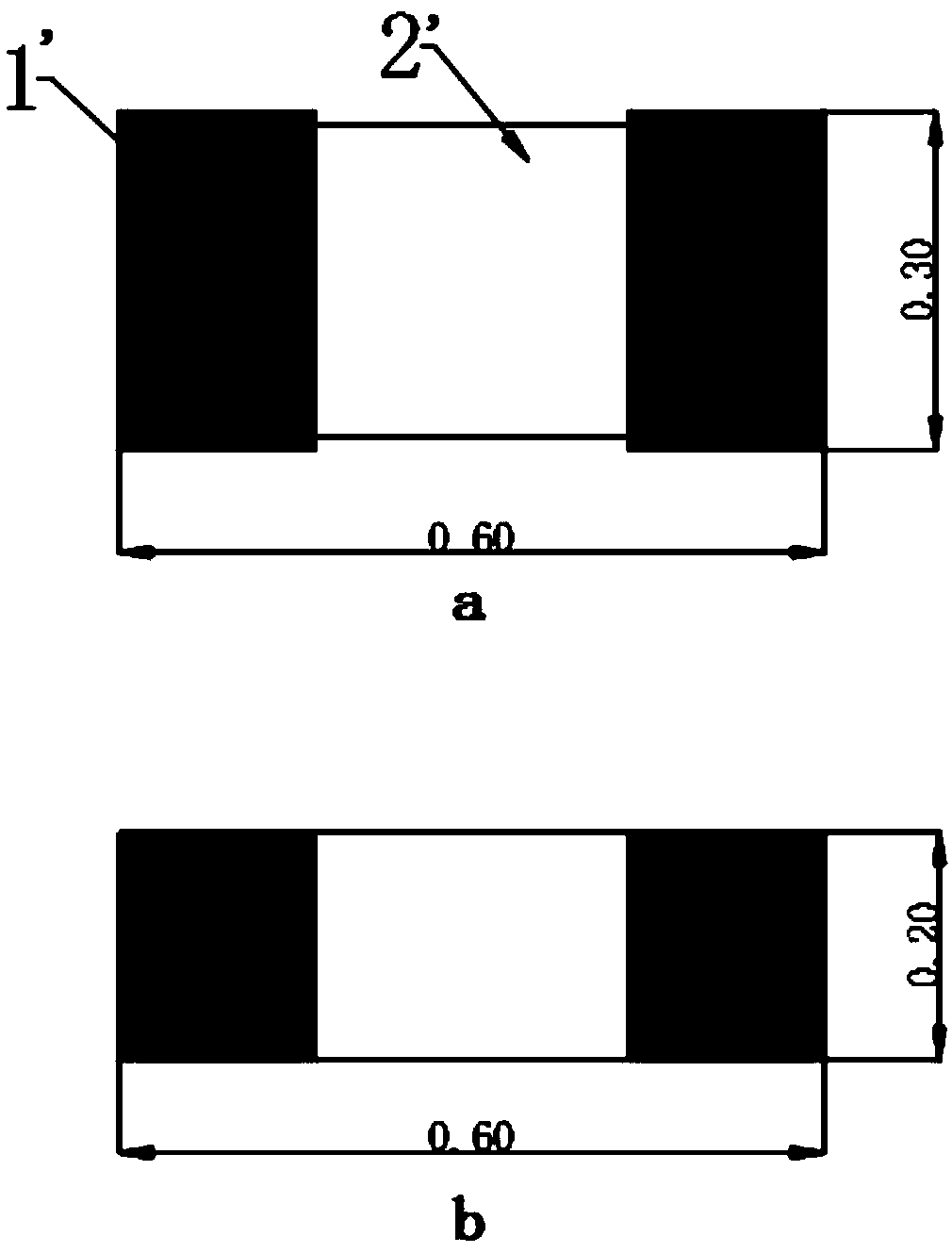
[0041] This embodiment provides a thin-film acquisition and transmission device for temperature signals, that is, a temperature detector, whose structure is as follows figure 2 with image 3 shown ( figure 2 The middle dotted line indicates that the length of the temperature detector can be determined according to the actual situation), including the thinned temperature sensor 6 and the planar transmission line, the thickness of the thinned temperature sensor 6 is less than 0.3mm, the thickness of the planar transmission line is less than 0.2mm, and the planar transmission line includes two The basic insulating layer 4 and the metal lead 3, the input electrode 1 and the output electrode 2 arranged between the two basic insulating layers 4, the metal lead 3 is a copper wire, one end of the metal lead 3 is connected to the input electrode 1, and the other end is connected to the output electrode 2. The output electrode 2 is connected to the processor, and the input electrode ...
Embodiment 2
[0052] The difference between this embodiment and embodiment 1 is: as Figure 4 As shown, the transmission line of the temperature detector includes an input electrode 1 and an output electrode 2. Both the input electrode 1 and the output electrode 2 are tinned pads of an 8-pin package, and the input pin of the input electrode 1 is connected to the The corresponding output pin of the output electrode 2 is connected.
[0053] In addition, in practical applications, the temperature detection sensor can use a negative temperature coefficient thermistor or a temperature acquisition chip, such as DS18B20, AD590, TMP35, TMP36 and other chips. If the temperature acquisition chip chooses SO surface mount package, it can also be used Grinding and thinning treatment, and then design the input and output electrodes that meet the package according to the specifications of the selected chip.
Embodiment 3
[0055] The difference between this embodiment and Embodiment 1 is that: taking a 15-inch LCD screen as an example, at least 4 sensors are required to accurately collect the temperature in the screen if the temperature in the screen is to be collected, and the 4 sensors are placed on the screen. The four corners are the most stable way to collect temperature. Such as Figure 5 As shown, a temperature detector using a thermistor as a sensor includes four input electrodes and four output electrodes, and the four input electrodes are input electrode one 1-1, input electrode two 1-2, input electrode two The third electrode 1-3, the fourth input electrode 1-4, and the four output electrodes are respectively the first output electrode 2-1, the second output electrode 2-2, the third output electrode 2-3, and the fourth output electrode 2-4. Each input electrode is welded with a temperature sensor, and the four temperature sensors are respectively arranged at the four corners of the l...
PUM
| Property | Measurement | Unit |
|---|---|---|
| thickness | aaaaa | aaaaa |
| thickness | aaaaa | aaaaa |
| thickness | aaaaa | aaaaa |
Abstract
Description
Claims
Application Information
 - R&D
- Intellectual Property
- Life Sciences
- Materials
- Tech Scout
- Unparalleled Data Quality
- Higher Quality Content
- 60% Fewer Hallucinations
Browse by: Latest US Patents, China's latest patents, Technical Efficacy Thesaurus, Application Domain, Technology Topic, Popular Technical Reports.
© 2025 PatSnap. All rights reserved.Legal|Privacy policy|Modern Slavery Act Transparency Statement|Sitemap|About US| Contact US: help@patsnap.com


