
Automatic marking device of large-capacity grating array optical cable and marking method of automatic marking device

A grating array and large-capacity technology, which is applied in the direction of light guides, optics, and optical components, can solve the problems of high marking accuracy and the inability of large-capacity grating array optical cables to accurately locate the position of the grating, and achieve high marking accuracy.

Inactive Publication Date: 2018-11-30
武汉烽理光电技术有限公司 +1
View PDF8 Cites 0 Cited by
  • Summary
  • Abstract
  • Description
  • Claims
  • Application Information

AI Technical Summary

Problems solved by technology

[0003] Aiming at the problem that the large-capacity grating array optical cable cannot accurately locate the position of the grating, the present invention proposes an automatic marking device and a marking method for the large-capacity grating array optical cable. The device can quickly, accurately and automatically mark the large-capacity grating array optical cable For grating point positioning and marking, it can adapt to grating arrays of different densities and lengths, with high marking accuracy

Method used


Image

  • Automatic marking device of large-capacity grating array optical cable and marking method of automatic marking device
  • Automatic marking device of large-capacity grating array optical cable and marking method of automatic marking device
  • Automatic marking device of large-capacity grating array optical cable and marking method of automatic marking device

Examples


Embodiment Construction

[0017] The present invention will be further described below in conjunction with drawings and embodiments.

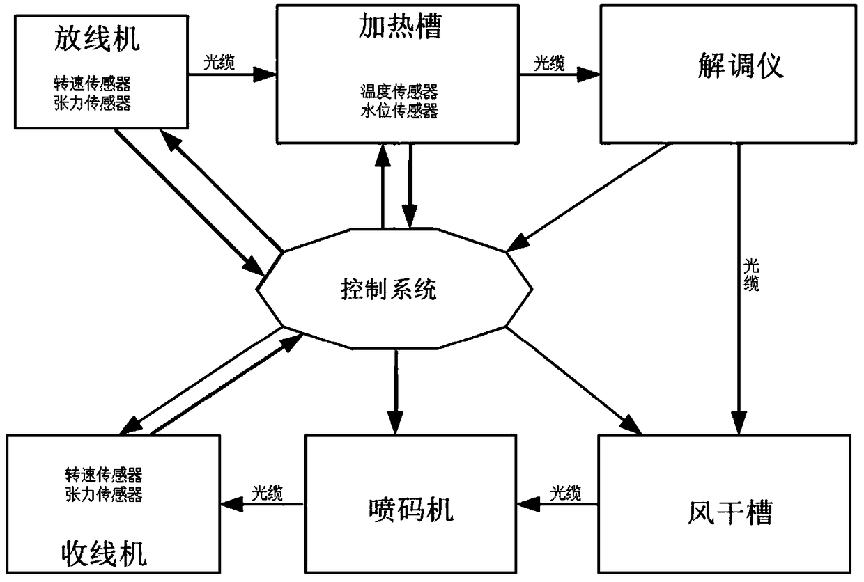
[0018] Such as figure 2 As shown, an automatic marking device for a large-capacity grating array optical cable includes a control system (in this embodiment, the control system is programmed using the labview platform, which is flexible in programming and has a high degree of visualization) and sequentially arranged along the route of the optical cable. A pay-off machine for laying out the optical cable, a heating tank for heating the optical cable through water, a demodulator for detecting the temperature of each grating point in the optical cable and recording the serial number of the grating point (in this embodiment, the demodulator The regulator adopts FBGDS-3000 from Wuhan Fengli Optoelectronics Technology Co., Ltd., a single channel can load 50,000 gratings, the temperature measurement accuracy reaches ±1°C, the spatial resolution is 1 meter, and the demodulatio...


PUM


Abstract

The invention relates to an automatic marking device of a large-capacity grating array optical cable and a marking method of the automatic marking device. The device comprises a control system, a pay-off machine, a heating groove, a demodulator, an air drying groove, an ink-jet printing machine and a take-up machine, wherein the pay-off machine, the heating groove, the demodulator, the air dryinggroove, the ink-jet printing machine and the take-up machine are sequentially arranged along the optical fiber. The control system can be used for adjusting take-up and pay-off speeds and tension of the take-up machine and the pay-off machine, a temperature and a water level of the heating groove and a cooling and air drying effect of the air drying groove; when a sequence number is recorded and send to the control system when that the temperature of a certain grating point reaches a threshold id detected by the demodulator, the control system controls the pay-off machine and the take-up machine to employ a slow speed mode, and the control system is used for controlling the ink-jet printing machine to performing ink-jet printing on the optical cable after the optical cable is slowed down and stepped for certain distance; and a warning is sent to the control system when that the sequence number of the grating point reaching the threshold is not continuous is detected by the demodulator,and the whole device is stopped by the control system. The device can be used for rapidly, accurately and automatically positioning and marking the grating point of the large-capacity grating array optical cable and is high in marking accuracy.

Description

technical field [0001] The invention belongs to the technical field of optical fiber gratings, and in particular relates to an automatic marking device and a marking method for a large-capacity grating array optical cable. Background technique [0002] Grating array technology is a new type of optical fiber sensing technology that has emerged in recent years. It uses wavelength division multiplexing (WDM) and optical time domain reflectometry (OTDR) technology to overcome the short detection distance and low spatial resolution of traditional fiber grating demodulation methods. Defects, its single-channel detection distance can reach up to 50 kilometers, and the spatial resolution can reach 10cm. It is the latest optical fiber sensing technology that combines the advantages of distributed optical fiber and fiber Bragg grating sensing technology. With the maturity and promotion of this technology, some problems have appeared one after another. For example, the number of gratin...

Claims


Application Information

Patent Timeline
Patent Type & Authority Applications(China)
IPC IPC(8): G02B6/44
CPCG02B6/4482
Inventor 李凯何光辉王月明徐一旻
Owner 武汉烽理光电技术有限公司
Learn More