
Adhering isolation layer prevention spraying equipment special for silicon rubber wires and cables

A technology for wire and cable and spraying equipment, applied in cable/conductor manufacturing, circuits, electrical components, etc., can solve problems such as uneven spraying, slow spraying speed, poor effect, etc., and achieve uniform spraying, low air consumption, and spraying feel. Oil even effect

Active Publication Date: 2018-11-30
张科
View PDF5 Cites 4 Cited by
  • Summary
  • Abstract
  • Description
  • Claims
  • Application Information

AI Technical Summary

Problems solved by technology

However, when the traditional spraying oil equipment is spraying the surface of the wire and cable, there are still problems such as slow spraying speed, uneven spraying, and poor effect.

Method used

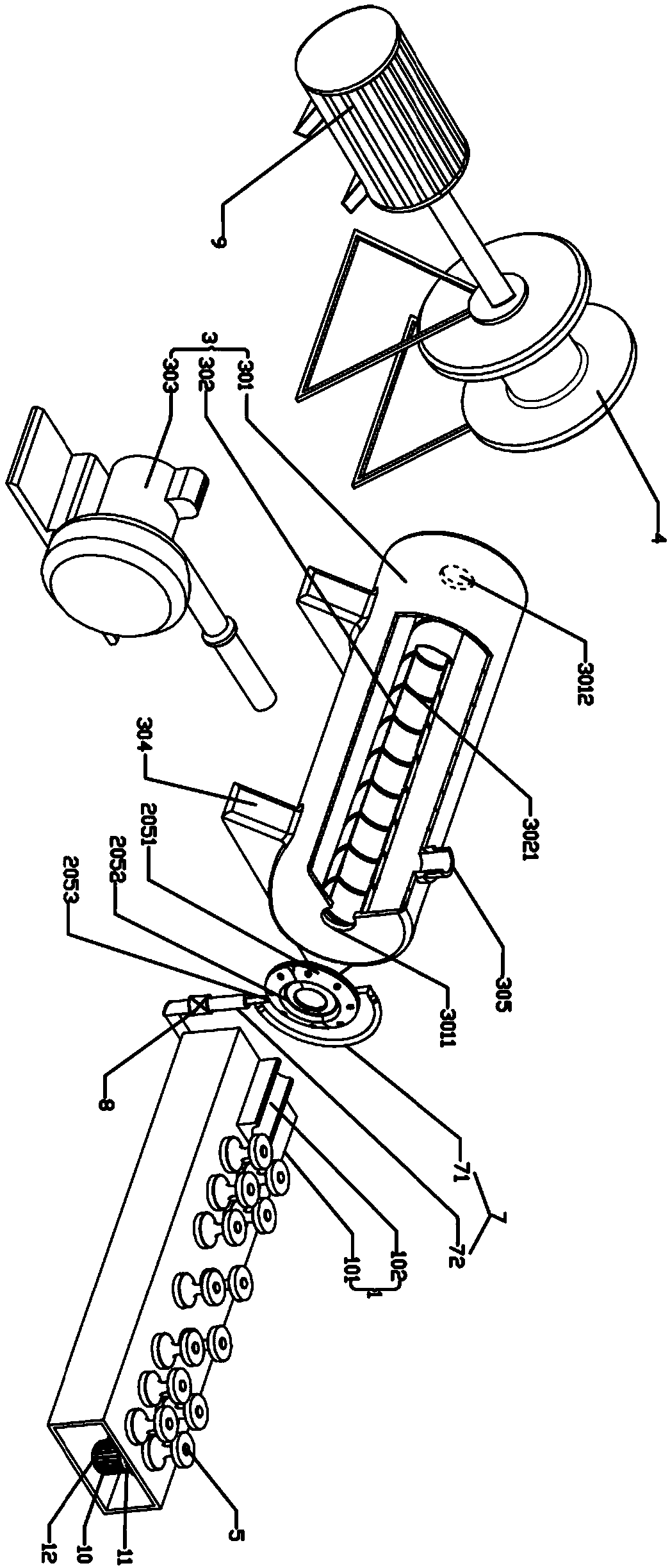

Image

  • Adhering isolation layer prevention spraying equipment special for silicon rubber wires and cables
  • Adhering isolation layer prevention spraying equipment special for silicon rubber wires and cables
  • Adhering isolation layer prevention spraying equipment special for silicon rubber wires and cables

Examples


Embodiment 1

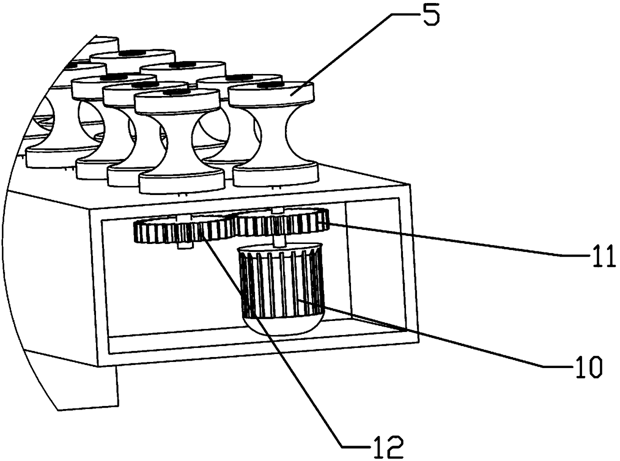
[0028] Example 1: Please also see Figure 1 to Figure 3 and Figure 6Embodiment 1 of the present invention provides a special spraying equipment for silicone rubber wire and cable, including a straightening mechanism 1, a spraying mechanism 2, an air-drying mechanism 3 and a winding mechanism 4; the straightening mechanism 1 includes a straightener body 101 and a Wire slot 102, two rows of straightening wheels 5 are arranged on the straightener body 101, the central axis of each row of straightening wheels 5 is located in the same plane, and each of the straightening wheels 5 and the straightening wheel The straightener body 101 is connected in rotation, and the straightening wheel 5 straightens the wires and cables to be sprayed to make the surface smoother, thereby ensuring more uniform spraying; the wire release trough 102 is fixedly installed on the straightening mechanism 1; The spraying mechanism 2 includes an oil storage tank 201, an atomizer 202, an air pump 203, an i...

Embodiment 2

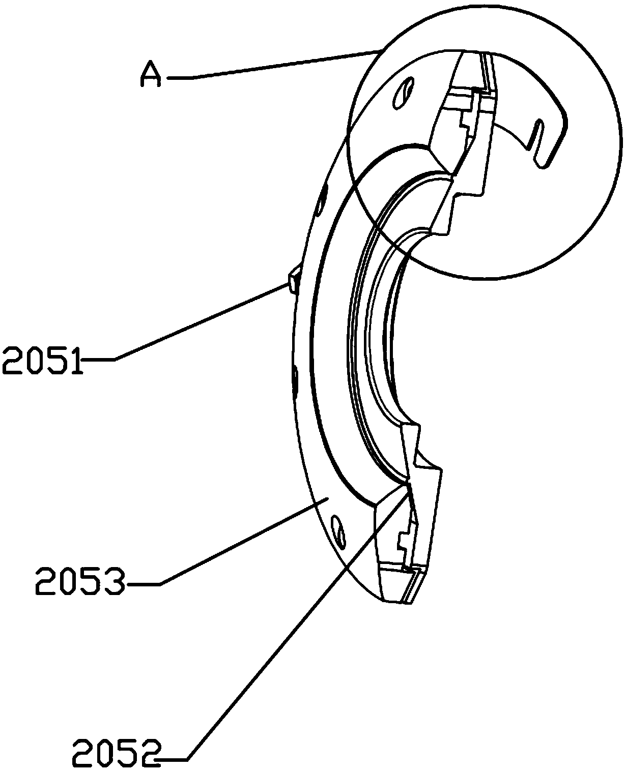
[0032] Embodiment 2: The difference with Embodiment 1 is that, as Figure 4 and Figure 5 As shown, the spraying mechanism 2 is provided with a protective cover 13 , and the protective cover 13 is placed between the straightening mechanism 1 and the air-drying mechanism 3 . Further, the protective cover 13 includes a base 131 and a baffle 132, the baffle 132 is arc-shaped, and one end of the baffle 132 is hinged to the base 131; the upper cover 1311 of the base 131 is circular Arc-shaped, the upper cover 1311 is set corresponding to the baffle 132 , the sample injection tube 7 passes through the upper cover 1311 , and the upper cover 1311 is provided with a plurality of leakage holes 1312 . The protective cover 13 can prevent the oil mist sprayed from the annular nozzle 25 from splashing and polluting the air and endangering human health; at the same time, the excess oil mist is blocked by the baffle plate 132, flows into the leakage hole 1312 after condensation, and can coll...


PUM


Abstract

The invention relates to the technical field of spraying equipment, and discloses an adhering isolation layer prevention spraying equipment special for silicon rubber wires and cables. The spraying equipment includes a straightening mechanism, a spraying mechanism, an air drying mechanism and a winding mechanism, wherein the spraying mechanism comprises an oil collector, an atomizer, an air pump,an integrated block and an annular nozzle, a liquid outlet of the oil collector communicates with a liquid inlet of the atomizer through a connecting pipe, and a liquid outlet of the atomizer and a liquid outlet of the air pump communicates with a liquid inlet of the integrated block; the annular nozzle is composed of two semi-annular nozzles, the two semi-annular nozzles are hinged, an annular air outlet is arranged on the inner ring surface of each semi-annular nozzle, and an injection port is arranged on the outer ring surface of each semi-annular nozzle; the injection ports communicate with a liquid outlet of the integrated block through sample inlet pipes, and the sample inlet pipe is provided with a regulating valve. The spraying equipment of the invention has more uniform spraying,better spraying effect, and the quality of wire and cable production is improved.

Description

technical field [0001] The invention relates to the technical field of spraying equipment, in particular to a spraying equipment for preventing adhesion and isolating layer specially used for silicone rubber wires and cables. Background technique [0002] Silicone rubber wire and cable is made of silicone material, which has excellent high and low temperature resistance, and can be used for a long time at -60°C to 180°C. At the same time, it also has good bending performance and anti-aging performance, and is not easy to damage and crack ,long lasting. Silicone rubber wires and cables are widely used in metallurgy, electric power, petrochemical, electronics, automobile manufacturing and other industries. [0003] After the production of silicon rubber wire and cable is completed, its chemical properties are not yet stable. If the silicone rubber wire and cable are arranged and extruded without an isolation layer, generally after 72 hours, the insulation layer or the sheath ...

Claims


Application Information

Patent Timeline
Patent Type & Authority Applications(China)
IPC IPC(8): H01B13/22H01B13/00
CPCH01B13/0036H01B13/227
Inventor 张科
Owner 张科
Learn More