
A backside structure for improving the backside efficiency of bifacial perc cells

A backside structure and battery technology, applied in circuits, electrical components, semiconductor devices, etc., can solve the problems of poor component stability, troublesome welding process, large shading area, etc., achieve stability improvement, reduce soldering points, and reduce shading area Effect

Active Publication Date: 2019-09-03
TONGWEI SOLAR (ANHUI) CO LTD
View PDF6 Cites 0 Cited by
  • Summary
  • Abstract
  • Description
  • Claims
  • Application Information

AI Technical Summary

Problems solved by technology

[0005] In the existing technology, there are still the following obvious defects in the method of improving the efficiency of the back of the PERC battery: 1. The current method of printing the back of the double-sided battery is to first print the back electrode on the first screen printing machine, and then print the back electrode on the second printing machine. Print the fine grid and main grid part of the aluminum grid line. The main grid part printed by this method is generally wider, the shading area is larger, and the current generated is less; 2. In addition, the contact resistance between aluminum and silicon is large, and the contact resistance The resistance also has a certain room for improvement; 3. In the later welding process of the ribbon, there are many welding points, the welding process is very troublesome, and the stability of the overall assembly after welding is poor, which needs to be improved

Method used


Image

  • A backside structure for improving the backside efficiency of bifacial perc cells
  • A backside structure for improving the backside efficiency of bifacial perc cells
  • A backside structure for improving the backside efficiency of bifacial perc cells

Examples


Embodiment Construction

[0029] The following will clearly and completely describe the technical solutions in the embodiments of the present invention with reference to the accompanying drawings in the embodiments of the present invention. Obviously, the described embodiments are only some, not all, embodiments of the present invention. Based on the embodiments of the present invention, all other embodiments obtained by persons of ordinary skill in the art without making creative efforts belong to the protection scope of the present invention.

[0030] see Figure 1-8 , the present invention provides a technical solution:

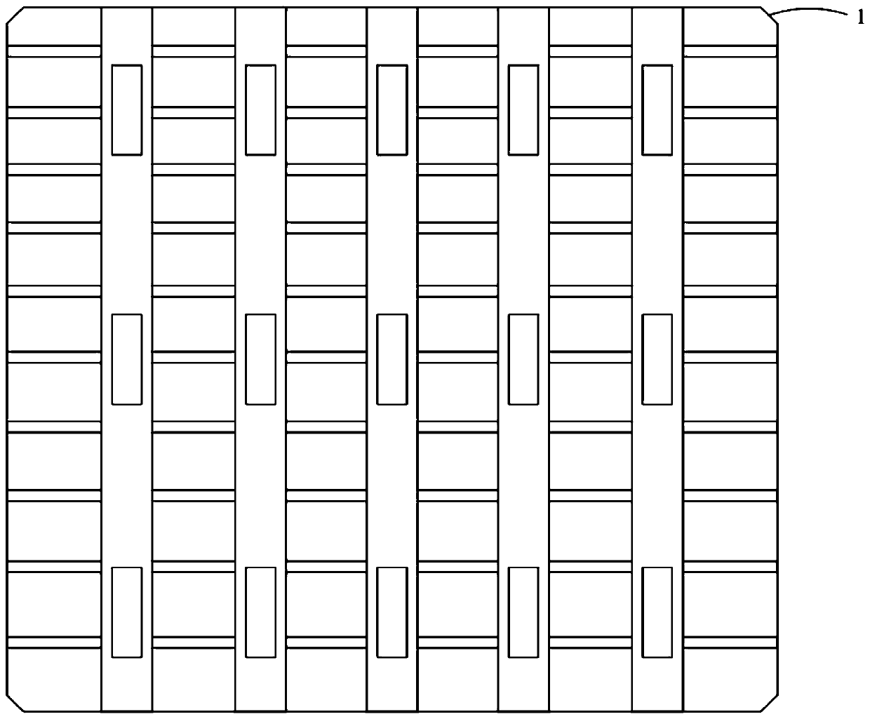
[0031] In the prior art, such as the attached figure 1 As shown, a main grid and a sub-grid are printed on the cell 1, and electrodes are printed on the main grid. In this way, the width of the main grid is wider, and the shading area is too large, which affects the photoelectric conversion efficiency of the cell.

[0032] A backside structure that improves the backside efficienc...


PUM


Abstract

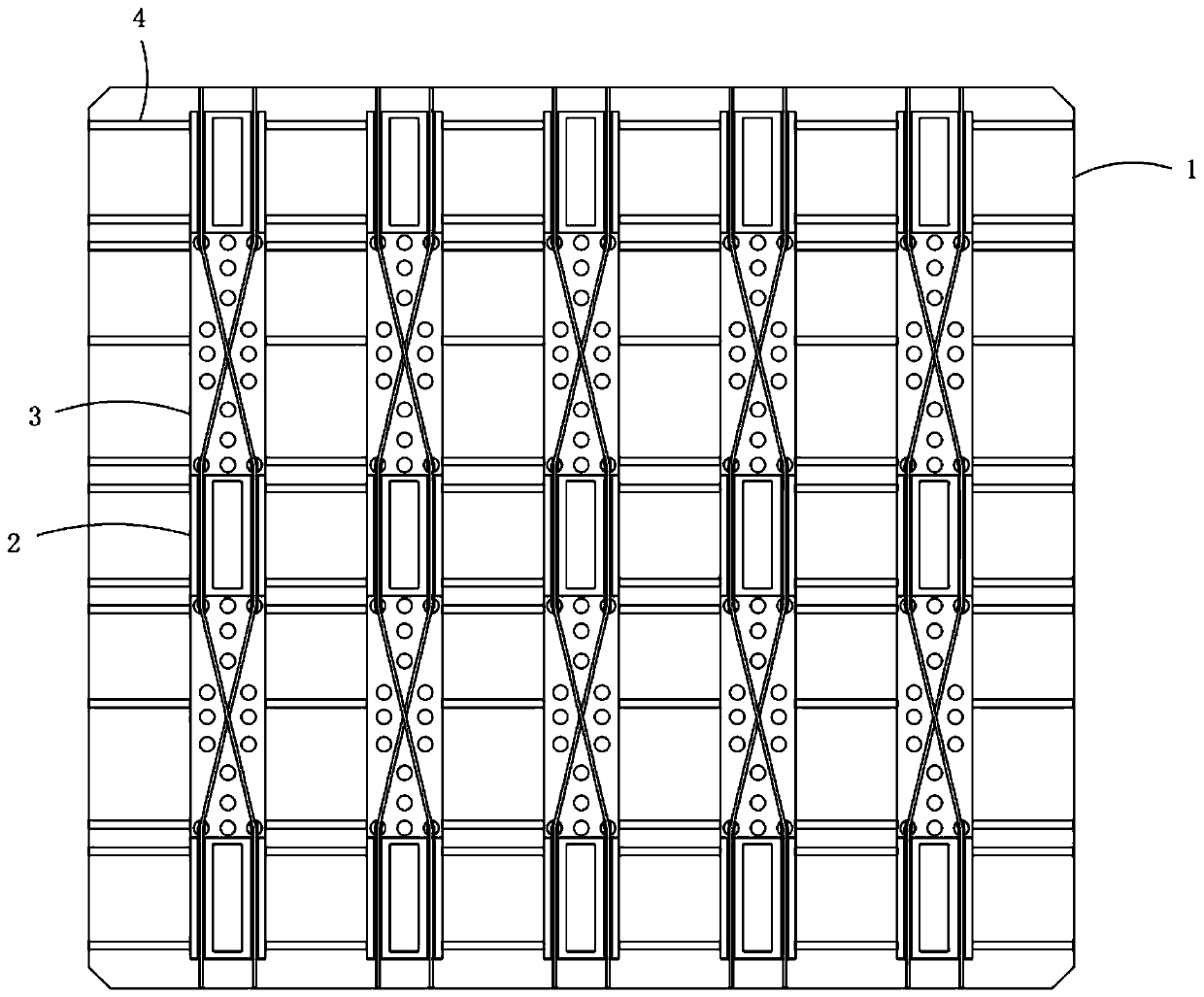
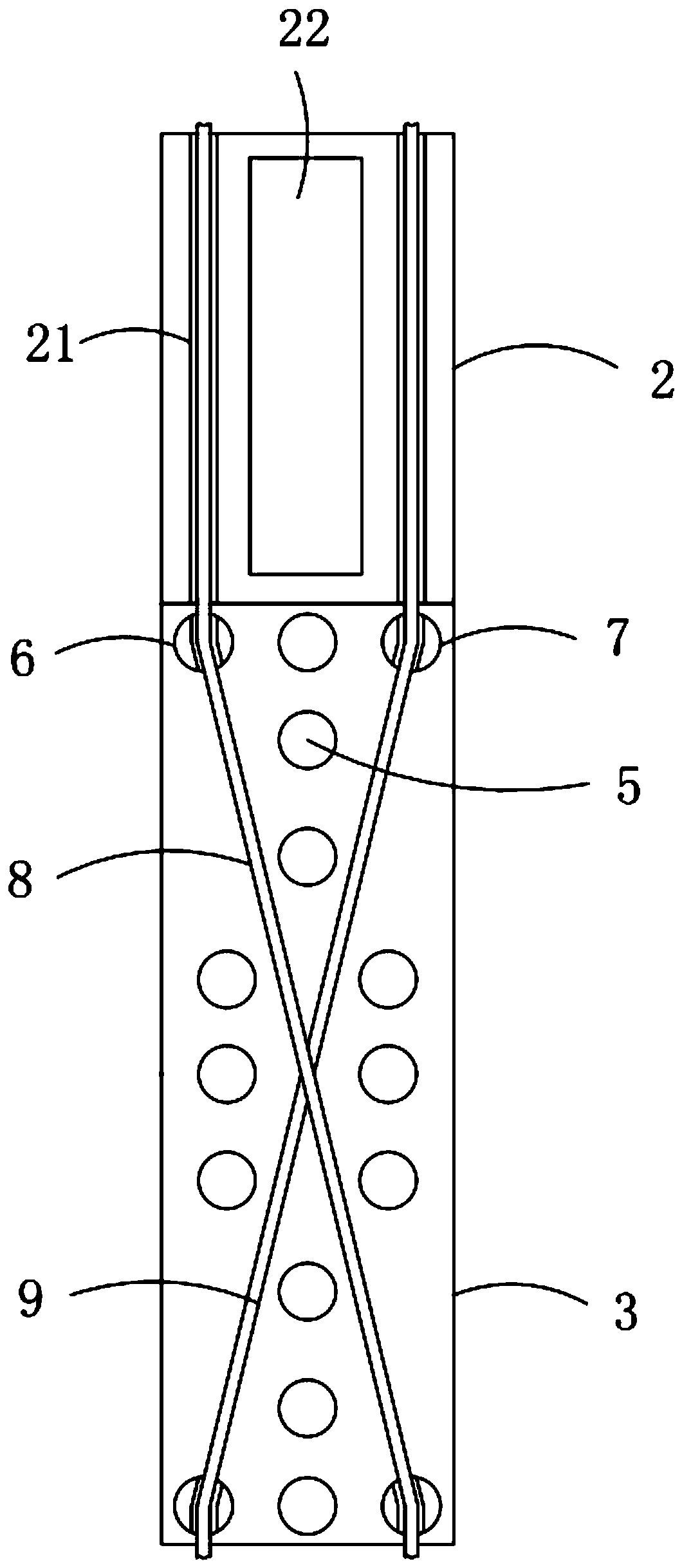
The invention discloses a back structure for improving a back efficiency of a double-sided PERC (Passivated Emitter and Rear Contact) cell, comprising a cell piece, wherein a back side of the cell piece is provided with a plurality of main grid lines in parallel, silver main grids and aluminum main grids are fixedly connected in an interval way, the length ratio between the silver main grid and the aluminum main grid is 1:2, conducting silver columns are inserted at four corners of the aluminum main grid in a penetrating way, the main grid lines are fixedly connected with high welding strips and low welding strips respectively, the high welding strips and the low welding strips on the silver main grids are arranged in parallel, and the high welding strips and the low welding strips on thealuminum main grids are arranged in a cross way. The back structure of the invention has the beneficial effects that: the width of a main grid part can be effectively reduced, thus the function of reducing a shading area can be achieved; the aluminum main grids which are conventionally used are replaced by the aluminum and silver main grids which are used in the interval way, so as to achieve lesscurrent loss in the way of reducing a contact resistance, and troublesome degree of welding can be reduced; in addition, stability after welding can be greatly improved, thus the back structure has high practicability, and is worth popularizing.

Description

technical field [0001] The invention relates to the technical field of photovoltaic modules, in particular to a back structure for improving the back efficiency of double-sided PERC cells. Background technique [0002] PERC (passivated emitter and back contact) technology is the most cost-effective means of improving the efficiency of crystalline silicon solar cells in recent years. It has high compatibility with conventional cell production lines, and the investment cost of production line transformation is low. The mainstream battery technology within the year. [0003] Double-sided PERC cells only slightly change the structure of PERC cells, changing the full-contact aluminum back field on the back to local aluminum grid lines, and the cost is comparable to that of single-sided PERC products. When packaged into double-glass modules, there is an additional 10%-30% Power generation gain is the future development trend of PERC components. [0004] The efficiency of the fro...

Claims


Application Information

Patent Timeline
Patent Type & Authority Patents(China)
IPC IPC(8): H01L31/0224
CPCH01L31/022441
Inventor 余波张鹏常青谢耀辉张元秋
Owner TONGWEI SOLAR (ANHUI) CO LTD
Learn More