MIMO airborne antenna adopting WiFi and LTE

A technology of antennas and antenna groups, which is applied in the direction of independent antenna unit combinations, antennas, antenna arrays, etc., can solve the problems of unfixed antenna installation position, equipment host position, small number of MIMO antenna units, and single antenna communication system, etc., to achieve improvement Effects of communication throughput, overall height reduction, and installation space saving

Pending Publication Date: 2018-11-30
CETC AVIONICS
View PDF0 Cites 2 Cited by
  • Summary
  • Abstract
  • Description
  • Claims
  • Application Information

AI Technical Summary

Problems solved by technology

[0005] The technical problem to be solved by the present invention is that the communication standard satisfied by the antenna is relatively single, the coverage of the antenna is small, and the number of MIMO antenna units is small, and the use of cables to connect external antenna devices may cause the installation position of the antenna to be different from the position of the device host. Fixed, the purpose is to provide a MIMO airborne antenna using WiFi and LTE to solve the above problems

Method used


Image

  • MIMO airborne antenna adopting WiFi and LTE

Examples


Embodiment 1

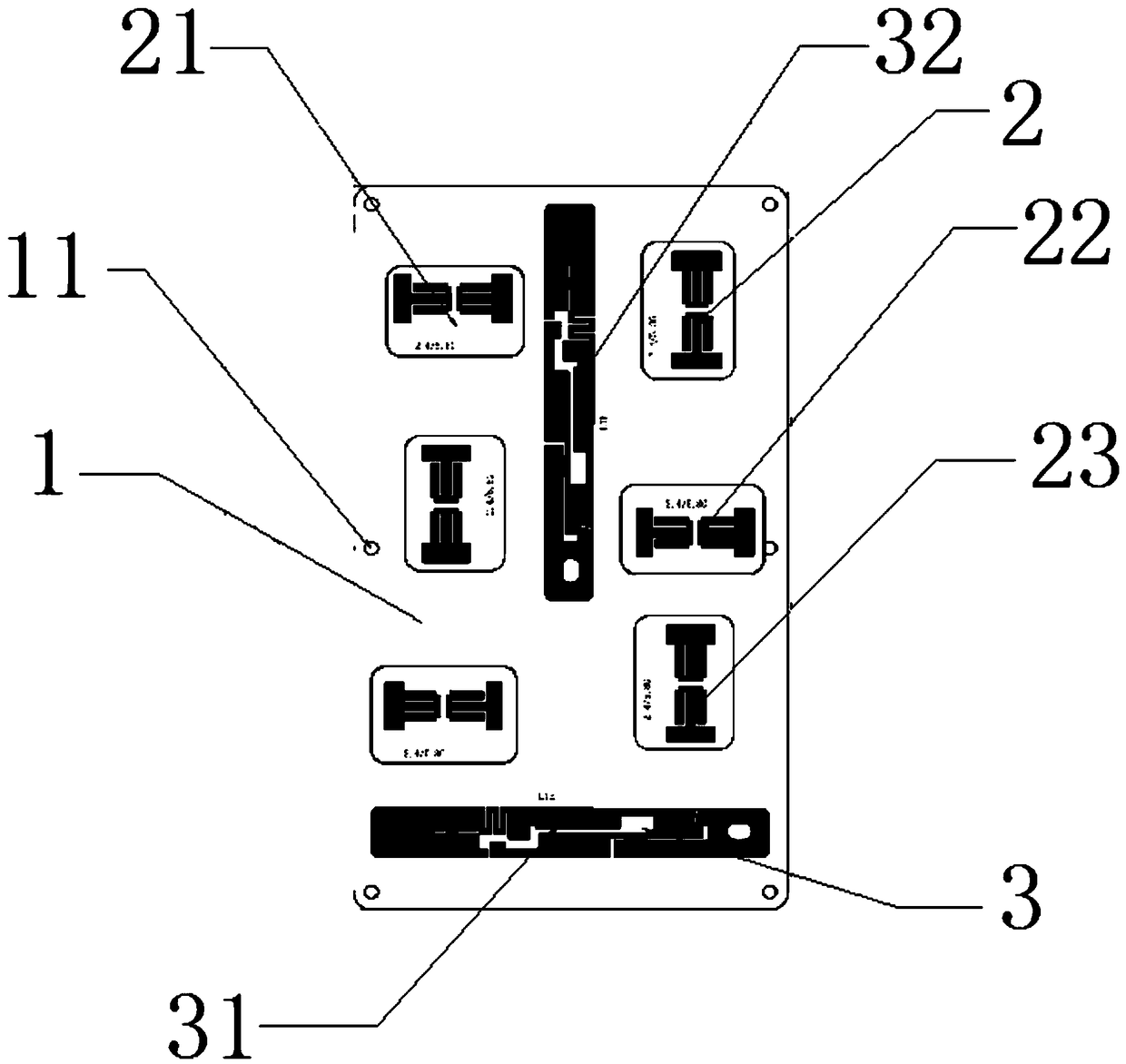
[0023] Such as figure 1 As shown, a MIMO airborne antenna adopting WiFi and LTE of the present invention includes several WiFi antenna unit array groups 2 and LTE antenna unit 3 arranged on the mounting board 1, and three WiFi antenna unit array groups 2 are arranged in the WiFi antenna unit array group 2. WiFi antennas 21, adjacent WiFi antennas 21 are vertically arranged from top to bottom, and the LTE antenna unit 3 includes a horizontal antenna 31 and a vertical antenna 32. The lower side of the upper end surface of the board 1 is parallel to the side, the vertical antenna 32 is perpendicular to the horizontal antenna 31, and the left and right sides of the vertical antenna 32 are respectively provided with a WiFi antenna unit array group 2, and two adjacent WiFi antenna unit array groups 2 The WiFi antennas 21 on the same horizontal line are perpendicular to each other. The technical problem to be solved by the present invention is mainly: to invent a new antenna for cab...

Embodiment 2

[0028]Screw holes 11 are provided on the end surface of the mounting plate 1 , and the mounting plate 1 is fixed in the nacelle through the screw holes 11 . Through the screw holes, the entire mounting plate can be fixed in the cabin to avoid the sliding of the mounting plate, which will affect the antennas on it, and then affect the signal.

[0029] The installation plate 1 has a length of at least 200mm and a width of at least 120mm. The antennas are mostly dipoles with flat plate reflections, requiring a height of 5-10 mm, and their width and length are preset to meet the setup of multiple antenna groups.

[0030] The frequency coverage ranges of the LTE horizontal antenna 31 and the LTE vertical antenna 32 are 0.7-1 GHz and 1.7-2.7 GHz.

[0031] The WiFi antenna unit array group has a total of 6 dual-band microstrip antennas, covering 2.4-2.5GHz and 5.15-5.85GHz, and each group has 3 antenna units.

Embodiment 3

[0033] This embodiment is optimized on the basis of Embodiment 1. By extending the length of the mounting board and installing WiFi antenna unit array groups of different frequencies on the mounting board, the frequency coverage and influence range of the entire airborne antenna can be effectively improved, and the use of figure 1 The arrangement can effectively make the antenna echoes interact with each other, increase the penetration effect, cover the entire cabin, and effectively penetrate the wall.


PUM


Abstract

The invention discloses an MIMO airborne antenna adopting WiFi and LTE. The antenna comprises a plurality of WiFi antennas and LTE antennas arranged on a mounting plate, wherein the WiFi antennas comprise a first antenna unit and a second antenna unit; the LTE antennas comprise a horizontal antenna and a vertical antenna, wherein the horizontal antenna is arranged on one side of the upper end faceof the mounting plate and is parallel to the lower side edge of the upper end face of the mounting plate; the vertical antenna is perpendicular to the horizontal antenna; and the first antenna unit of the vertical antenna is separated from the second antenna unit. The technical problem to be solved by the invention is as follows: the novel antenna for passenger cabin coverage is used for improving the existing antenna defect, the antenna coverage performance of the wireless equipment on the aircraft is improved, the electromagnetic compatibility performance of the equipment is improved, and the consistency, reliability and installation convenience of equipment are ensured.

Description

technical field [0001] The invention relates to an airborne antenna, in particular to a MIMO airborne antenna using WiFi and LTE. Background technique [0002] Airborne antennas usually not only need to be compatible with the installation position and structure of the airframe, but also must be electromagnetically compatible with all airborne antennas and the airframe, and compatible with the use environment. [0003] At present, the existing airborne antennas mainly include the following three types: [0004] Microstrip antenna. Specifically, on a thin dielectric substrate, a thin metal layer is attached on one side as a ground plane, and a metal patch of a certain shape is made on the other side by photolithography and etching, and the patch is fed by a microstrip line or a coaxial probe. electricity, thus forming an antenna. The microstrip antenna has the advantages of low profile, small size, light weight, low cost, and easy mass production, and due to the emergence o...

Claims


Application Information

Patent Timeline
Patent Type & Authority Applications(China)
IPC IPC(8): H01Q1/12H01Q5/10H01Q5/20H01Q21/00H01Q21/30
CPCH01Q21/00H01Q1/12H01Q5/10H01Q5/20H01Q21/30
Inventor 杜晓实鄢勇
Owner CETC AVIONICS
Why Eureka
Try Eureka