Integrated gear chamber

A gear chamber and integrated technology, which is applied in the direction of pressure lubrication of lubrication pumps, engine components, machines/engines, etc., can solve the problems of low integration of parts, many parts stacked, and large space occupation, so as to reduce costs And assembly difficulty and strength, reduce the number of parts, the effect of simple and reasonable structure

Active Publication Date: 2018-12-04
GUANGXI YUCHAI MASCH CO LTD
View PDF8 Cites 1 Cited by
  • Summary
  • Abstract
  • Description
  • Claims
  • Application Information

AI Technical Summary

Problems solved by technology

The traditional gear chamber design is not compact, the function is single, the degree of parts integration is not high, the shape is more complicated and unsightly, and the parts are stacked more, which can only realize the basic functions of the gear chamber and cannot meet the needs of the engine layout. parts integration
[0003] The gear chamber in the prior art has the following disadvantages: 1. The gear chamber is simply used as a cavity for assembling closed gears, and has a single function; 2. For the peripheral assembly accessories, it is necessary to add brackets, brackets, etc., and add multiple parts to cooperate. It is inconvenient to improve the production cycle; 3. There are many installation parts, taking up a lot of space, not compact and beautiful; 4. The layout of the front end of the entire engine will appear messy, especially when one engine is equipped with multiple models, it will be different due to various models. According to the needs of the engine, many different arrangements are produced correspondingly, which brings a lot of inconvenience to the supporting development of the engine.

Method used


Image

  • Integrated gear chamber
  • Integrated gear chamber

Examples


Embodiment Construction

[0015] The specific embodiments of the present invention will be described in detail below in conjunction with the accompanying drawings, but it should be understood that the protection scope of the present invention is not limited by the specific embodiments.

[0016] Unless expressly stated otherwise, throughout the specification and claims, the term "comprise" or variations thereof such as "includes" or "includes" and the like will be understood to include the stated elements or constituents, and not Other elements or other components are not excluded.

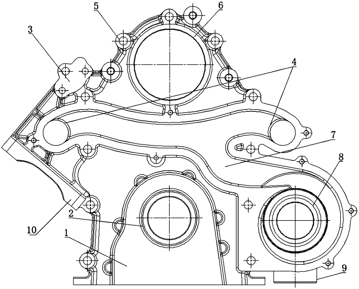
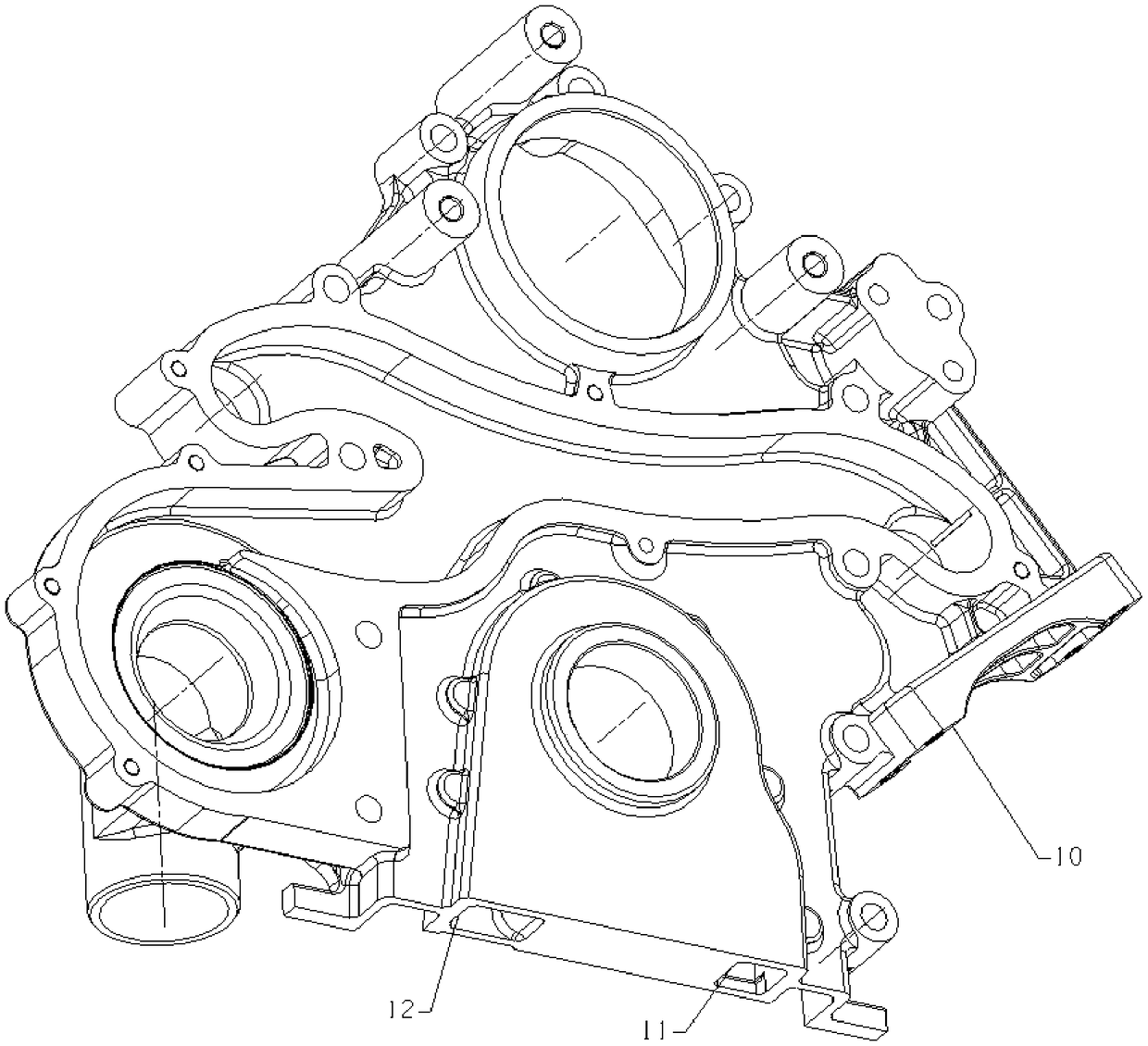
[0017] like figure 1 as shown, figure 1 It is a front structural schematic diagram of an integrated gear chamber according to an embodiment of the present invention, figure 2 It is a schematic diagram of the three-dimensional structure of the integrated gear chamber according to an embodiment of the present invention.

[0018] An integrated gear chamber according to a preferred embodiment of the present invention includ...


PUM


Abstract

The invention discloses an integrated gear chamber. The integrated gear chamber comprises a gear chamber body, a mounting boss, a fuel injection pump mounting hole, a water pump and a water return hole are integrated in the gear chamber body, wherein the mounting boss is arranged above one end of the gear chamber body and is used for allowing an idler or a tensioning wheel to be installed, the fuel injection pump mounting hole is formed in the top of the gear chamber body, and is used for allowing a fuel injection pump to be installed, the water pump is arranged at the other end of the gear chamber body, moreover, a plurality of water inlets are formed in the inclined upper portion of the water pump, a water inlet pipe of the water pump is vertically protruded from the water pump downwards, water inlet of the water pump is achieved through the water inlet pipe, water enters the plurality of water inlets through a water cavity, then the water enters an air cylinder body from the plurality of water inlets, and return water of the air cylinder body is returned to the water inlet pipe of the water pump through the water return hole. Therefore, the integrated gear chamber is simple andreasonable in structure, the number of parts is reduced, the arrangement is convenient, and the cost and the assembly difficulty and strength are reduced.

Description

technical field [0001] The invention relates to the field of engine components, in particular to an integrated gear chamber. Background technique [0002] The gear chamber is one of the main parts of the engine, and it is the working chamber of the engine gear transmission system, which plays the role of protection, sealing, vibration reduction and noise reduction. The traditional gear chamber design is not compact, the function is single, the degree of parts integration is not high, the shape is more complicated and unsightly, and the parts are stacked more, which can only realize the basic functions of the gear chamber and cannot meet the needs of the engine layout. components to achieve parts integration. [0003] The gear chamber in the prior art has the following disadvantages: 1. The gear chamber is simply used as a cavity for assembling closed gears, and has a single function; 2. For the peripheral assembly accessories, it is necessary to add brackets, brackets, etc....

Claims


Application Information

Patent Timeline
Patent Type & Authority Applications(China)
IPC IPC(8): F02F7/00F01M1/02
CPCF01M1/02F02F7/0021F02F7/0043F02F7/0073
Inventor 廖升友余锦海覃文刘治春覃壮革谷峪
Owner GUANGXI YUCHAI MASCH CO LTD
Why Eureka
Try Eureka