Motor control apparatus

A control device and motor technology, which is applied in motor control, AC motor deceleration device, circuit device, etc., to prevent overvoltage damage and prevent abnormal short-circuit up and down

Active Publication Date: 2018-12-04
MITSUBISHI ELECTRIC CORP
View PDF5 Cites 5 Cited by
  • Summary
  • Abstract
  • Description
  • Claims
  • Application Information

AI Technical Summary

Problems solved by technology

When the inverter abnormality detection unit 108 generates an abnormality detection signal, the third protection circuit 203 operates, and the three-phase short circuit performed by the second protection circuits 202a and 202b becomes invalid.

Method used


Image

  • Motor control apparatus
  • Motor control apparatus
  • Motor control apparatus

Examples


Embodiment approach 1

[0068] (1) Detailed description of the structure

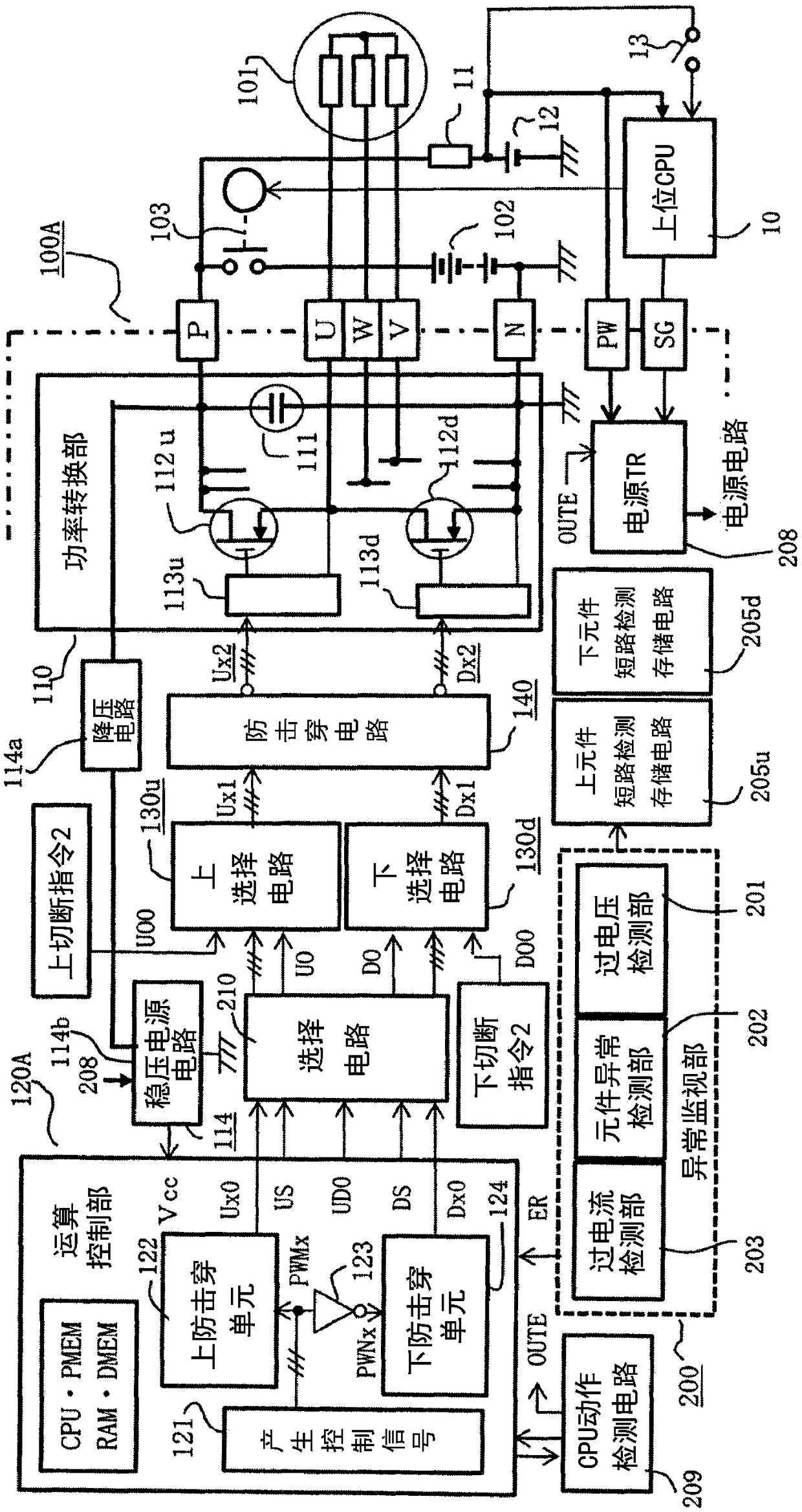
[0069] Hereinafter, the motor control device according to the first embodiment of the present invention will be described in detail with reference to the drawings. figure 1 It is an overall circuit block diagram of the motor control device according to Embodiment 1 of the present invention. in figure 1 Here, the motor control device 100A includes a power conversion unit 110, an arithmetic control unit 120A, and an abnormality monitoring unit 200. The positive side power supply terminal P and the negative side power supply terminal N are connected to a low-voltage system such as DC48V [V] via a power switching element 103. The battery 102 is connected. In addition, the maximum charging voltage of the in-vehicle battery 102 is less than DC60 [V], and it is configured to have a limit voltage that does not cause an electric shock hazard.

[0070] The AC terminals U, V, and W provided in the power conversion unit 110 are connected to...

Embodiment approach 2

[0196] (1) Detailed description of structure and function

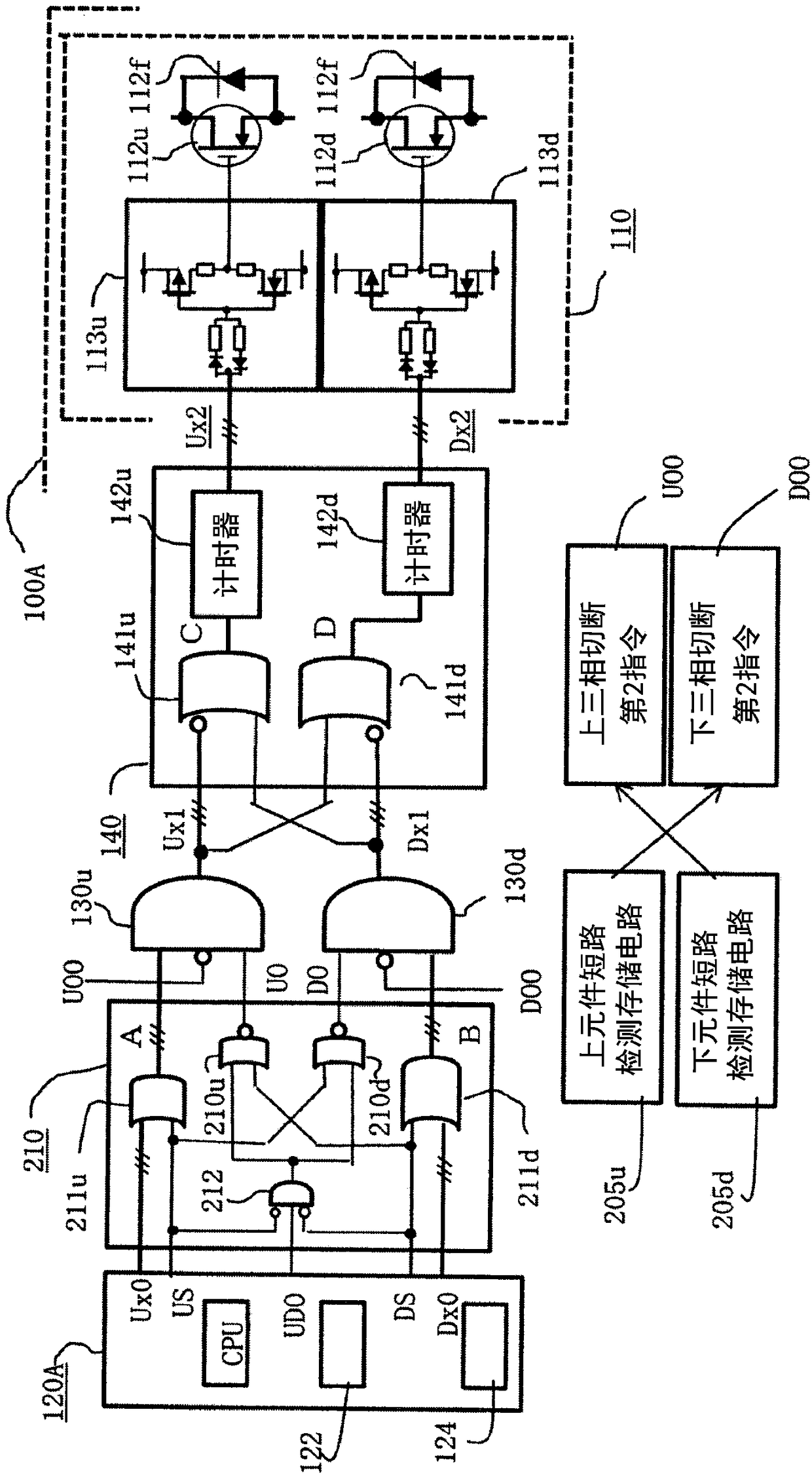
[0197] Hereinafter, the motor control device according to Embodiment 2 of the present invention will be described in detail. Figure 5 Is an overall circuit block diagram of the motor control device according to the second embodiment of the present invention, Image 6 It is a detailed block diagram of a part of the motor control device according to the second embodiment of the present invention. In addition, in each figure, the same reference numerals indicate the same or equivalent parts, but the motor control device 100A in the first embodiment is represented as the motor control device 100B in the second embodiment, and the capital letters at the end of the reference numerals indicate the embodiments The difference.

[0198] in Figure 5 in, Figure 5 versus figure 1 The main differences are only: Figure 5 The motor control device 100B in figure 1 Between the breakdown prevention circuit 140 and the power conversion ...


PUM


Abstract

The invention discloses a motor control apparatus used for restraining the occurrence of overvoltage abnormity and preventing circuit components from being damaged. An upper switching device and a lower switching device in an electric-power conversion unit are separately driven to close by an upper closing command signal and a lower closing command signal, respectively, generated by a calculationcontrol unit; in response to occurrence of an excessive current abnormality or an excessive voltage abnormality, upper and lower selection circuits and a penetration prevention circuit provided in a signal path select an upper three-phase short-circuiting command signal or a lower three-phase short-circuiting command signal, or an upper-and-lower six-phase cutoff command signal, and a penetrationprevention time prohibits upper and lower switching devices from being concurrently closed; when an excessive voltage abnormality occurs, the three-phase short-circuiting command signal is immediatelygenerated, without an advanced cutoff operation being performed. As a result, excessive-voltage breakage of the circuit components is prevented.

Description

Technical field [0001] The present invention relates to a motor control device for a three-phase AC motor that cooperates with an on-vehicle engine for driving a vehicle, and more particularly to an improvement of a motor control device that uses a low-voltage system on-vehicle battery to prevent electric shock. Background technique [0002] In a hybrid vehicle using an internal combustion engine and an electric motor, the arithmetic control unit drives and controls the three-phase AC motor powered by the on-board battery via a power conversion unit that uses transistors to form a three-phase full-wave bridge circuit. The arithmetic control unit constitutes In order to set the motor rotation speed indicated by the host microprocessor and the drive current corresponding to the shared load torque between the engines, the power drive control of the motor is performed, and the on-board battery is regeneratively charged. If the charging voltage is appropriate, the idling control of re...

Claims


Application Information

Patent Timeline
Patent Type & Authority Applications(China)
IPC IPC(8): H02P29/024H02J7/14
CPCH02J7/14H02P29/0241H02P3/22H02P29/027
Inventor 森武直纪木村友博益留一成
Owner MITSUBISHI ELECTRIC CORP
Why Eureka
Try Eureka