
Ship engine room temporary ventilation method

A ventilation method and engine room technology, applied in hull ventilation/heating/cooling, ship construction, ship design, etc., can solve problems such as reduced production efficiency, harsh operating environment, and difficult ventilation, and reduce the impact of height and gas weight. The effect of purifying the construction work environment and increasing the speed

Active Publication Date: 2018-12-07
GUANGZHOU SHIPYARD INTERNATIONAL LTD
View PDF19 Cites 4 Cited by
  • Summary
  • Abstract
  • Description
  • Claims
  • Application Information

AI Technical Summary

Problems solved by technology

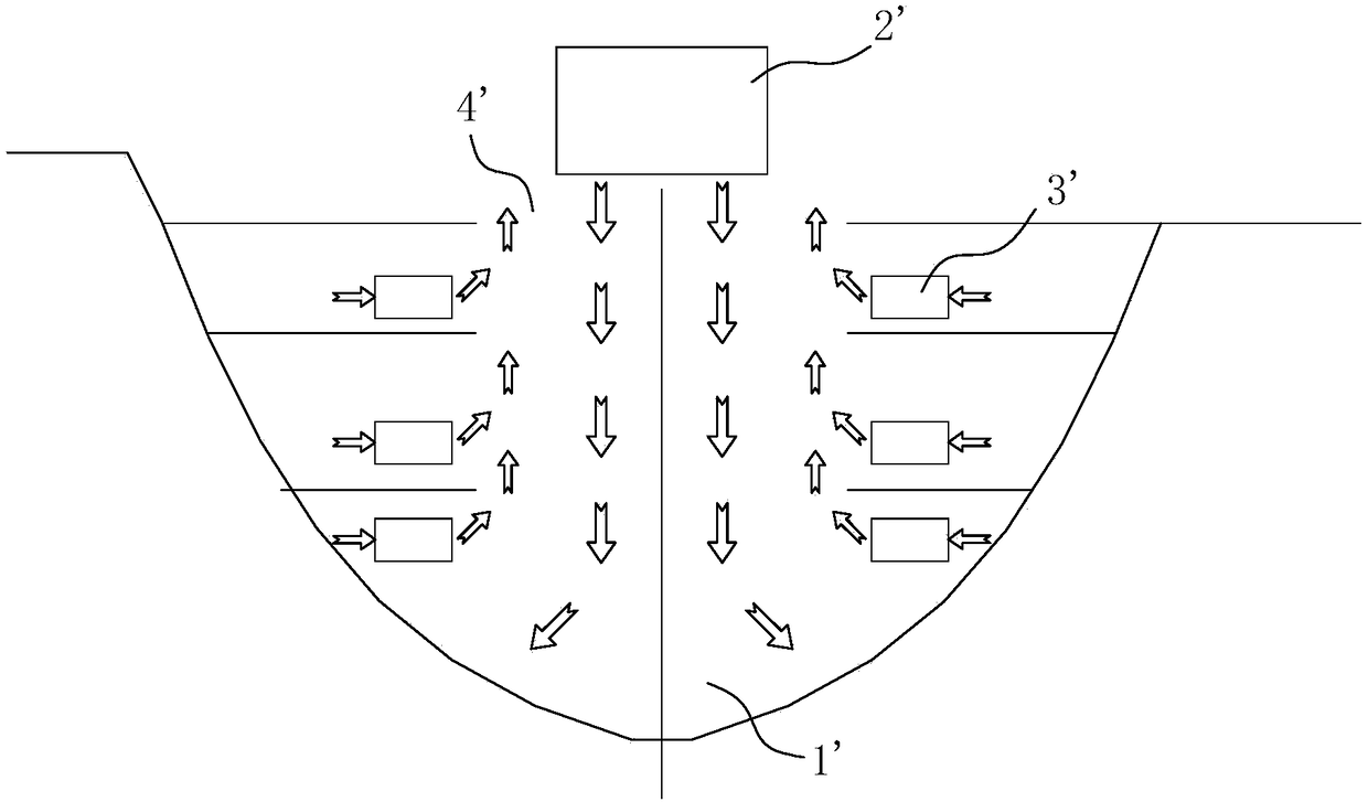
However, because the dust in the gas has a certain weight, and the distance between the bottom of the engine room and the main deck is usually greater than ten meters, the weight of the dust and the structure of the engine room make it easy to blow air from top to bottom during the ventilation process, while from It is very difficult to draw air up and down
Through the above-mentioned ventilation method, a large amount of gas in the cabin cavity 1' cannot be effectively discharged from the outside of the cabin, causing it to accumulate at the bottom of the cabin
There is a large amount of harmful gas mixed with dust in the engine room, which makes the working environment of the inner cavity 1' of the engine room harsh. After the construction personnel inhale a large amount of harmful gas mixed with dust during operation in the inner cavity 1' of the engine room, it will cause great harm to the human body. In a short period of time, it will reduce the immunity of the human body and reduce production efficiency, while construction workers who work for a long time are prone to occupational diseases such as tuberculosis

Method used


Image

  • Ship engine room temporary ventilation method
  • Ship engine room temporary ventilation method

Examples


Embodiment Construction

[0024] The technical solutions of the present invention will be further described below in conjunction with the accompanying drawings and through specific implementation methods.

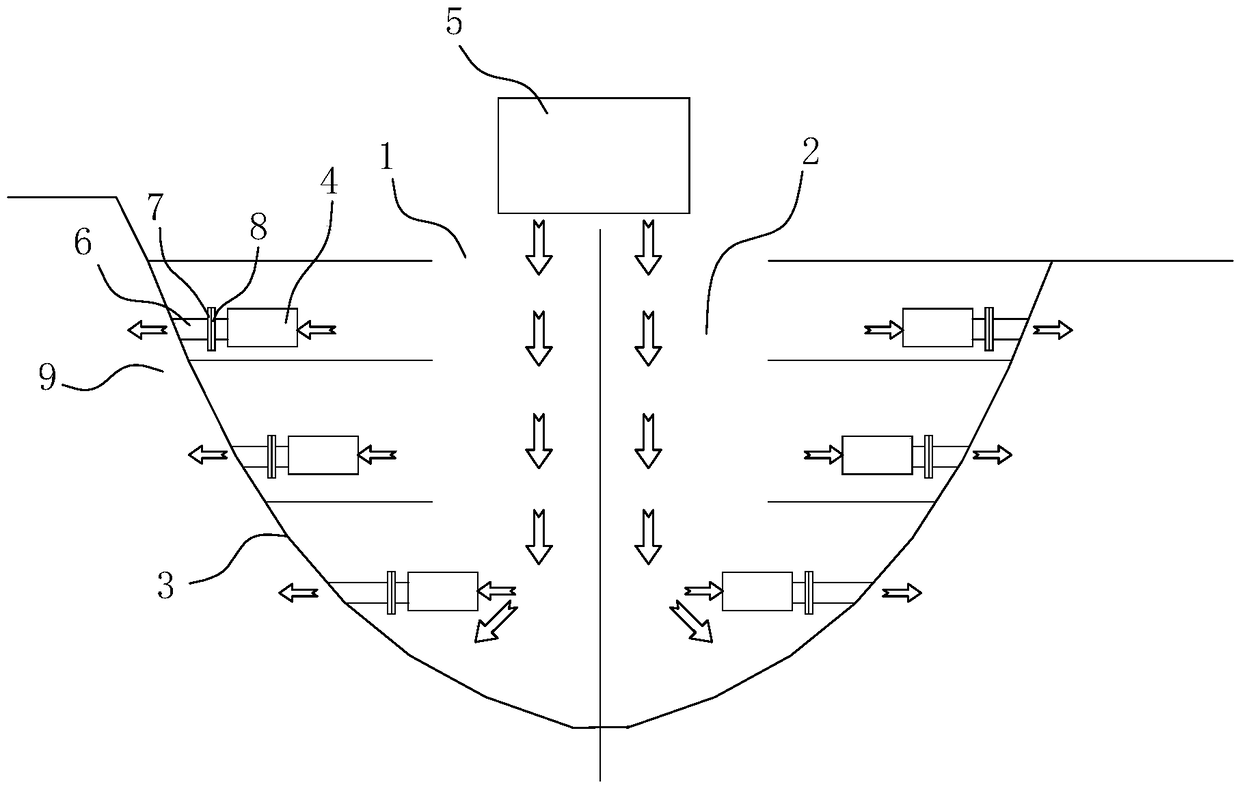
[0025] Such as figure 2 As shown, among them, figure 2 The arrows in the figure represent the flow direction of the gas. In this embodiment, a temporary ventilation method for a ship engine room according to the present invention is provided with a side pipe 6 on the side wall 3 of the engine room, and the side pipe 6 Connect the outside of the engine room with the engine room cavity 2, temporarily install a pipeline exhaust fan 4 near the end of the engine room cavity 2 on the side pipe 6, and the pipeline exhaust fan 4 is used to remove the engine room cavity 2 The gas in the engine room is pumped through the side pipe 6 to the outside 9 of the engine room.

[0026] After the main hull of the ship is carried and formed, a semi-closed engine room is formed. In the present embodiment, the size o...


PUM


Abstract

The invention discloses a ship engine room temporary ventilation method. A side pipe is arrange on A side wall of an engine room, the side pipe communicates with the exterior of the engine room and aninner cavity of the engine room, a pipe suction fan is temporarily installed at one end of the side pipe close to the inner cavity of the engine room, and the pipe suction fan is used for pumping thegas in the engine room to the outside of the engine room through the side pipe. According to the ship engine room temporary ventilation method, the pipe suction fan is temporarily installed at one end of the side pipe, the harmful gases mixed with dust in the inner cavity of the engine room are pumped out from the side pipe to the outside of the engine room, the method avoids discharging toxic gas mixed with dust in the inner cavity of the engine room cavity through an engine room opening, reduces the influence of the engine room cavity height and the gas weight, reduces the difficulty of discharging the gas, improves the gas discharging rate, strengthens the air circulation of the inner cavity of the engine room, and purifies the construction working environment of the inner cavity of the engine room.

Description

technical field [0001] The invention relates to the technical field of ships, in particular to a temporary ventilation method for a ship engine room. Background technique [0002] Currently, after the main hull of the ship is formed, a semi-enclosed compartment is formed inside the engine room. The engine room of the formed main hull needs a lot of assembly, welding and grinding construction operations, and a large amount of harmful dust will be generated during the construction work in the engine room, and the engine room needs to be temporarily ventilated. [0003] Existing methods for temporary ventilation in the cabin such as figure 1 As shown, by setting the air intake fan 2' for the outside of the nacelle to the nacelle inner chamber 1' directly above the nacelle opening 4', and setting the exhaust fan 3' on each layer of the nacelle side wall, using the air draft The engine 3' discharges the toxic gas mixed with dust in the engine room cavity 1' to the outside of th...

Claims


Application Information

Patent Timeline
IPC IPC(8): B63B9/00B63J2/02
CPCB63J2/02B63B71/00
Inventor 肖锦强
Owner GUANGZHOU SHIPYARD INTERNATIONAL LTD
Learn More