
Energy-efficient intermediate cooling and heat exchange system for seed decomposition

A heat exchange system and energy-saving technology, applied in indirect heat exchangers, heat exchanger types, heat exchange equipment, etc., can solve the problems of high energy consumption and complex flushing process of plate heat exchangers, and achieve obvious advantages and energy saving. Significant consumption reduction

Inactive Publication Date: 2018-12-07
SHENYANG ALUMINIUM MAGNESIUM INSTITUTE
View PDF3 Cites 0 Cited by
  • Summary
  • Abstract
  • Description
  • Claims
  • Application Information

AI Technical Summary

Problems solved by technology

The seed decomposition production process requires intermediate cooling of the aluminum hydroxide slurry. Wide-channel plate heat exchangers or spiral plate heat exchangers are generally used as intermediate cooling equipment. Although plate heat exchangers have the characteristics of high heat transfer efficiency, However, it needs to be equipped with a feeding pump. In addition, the plate heat exchanger needs to be washed with alkali and mother liquor regularly, and it needs to be equipped with a corresponding alkali wash mother liquor flushing process.
Therefore, the intermediate cooling of the plate heat exchanger has the disadvantages of high energy consumption and complicated flushing process

Method used


Image

  • Energy-efficient intermediate cooling and heat exchange system for seed decomposition
  • Energy-efficient intermediate cooling and heat exchange system for seed decomposition
  • Energy-efficient intermediate cooling and heat exchange system for seed decomposition

Examples


Embodiment Construction

[0018] The present invention will be further described below in conjunction with accompanying drawing.

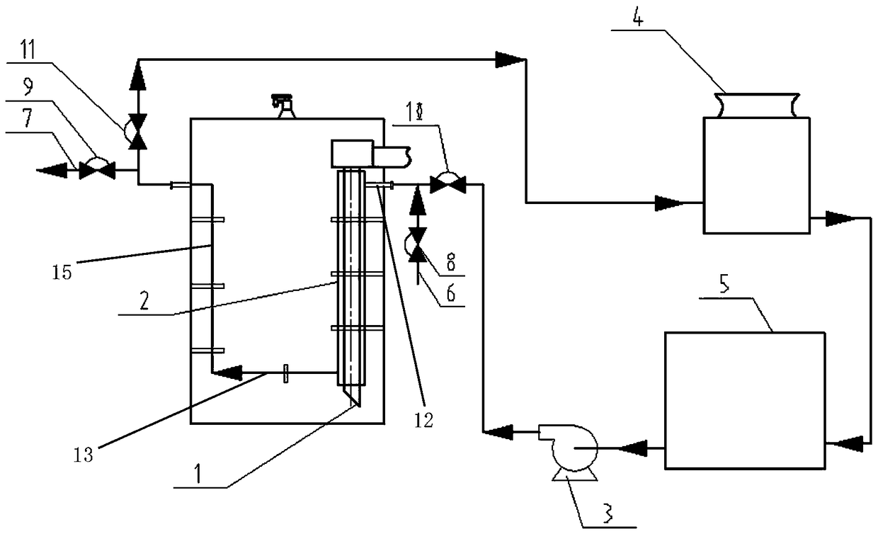
[0019] As shown in the figure, the present invention is a high-efficiency energy-saving intermediate cooling and heat exchange system for seed separation. There is a material lifting pipe 1 in the seed separation tank, and a heat exchange sleeve 2 is arranged outside the material lifting pipe 1. On the heat exchange sleeve 2 There are circulating water inlet 12 and circulating water return pipe 13. The circulating upper water pipe 12 is located at the top of the heat exchange sleeve 2, and the circulating return water pipe 13 is located at the bottom of the heat exchange sleeve 2. The circulating return water pipe 13 passes through the pipeline and the cooling tower 4 in communication, the cooling tower 4 communicates with the cold water pool 5 through pipelines, and the cold water pool 5 communicates with the circulating upper water nozzle 12 through pipelines.

[0020] Fi...


PUM


Abstract

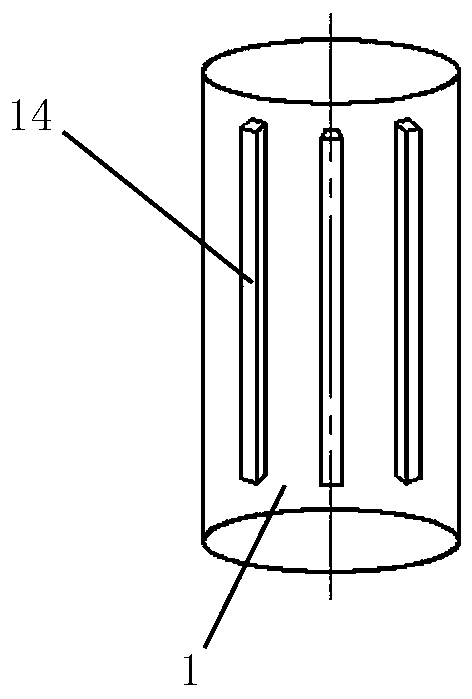
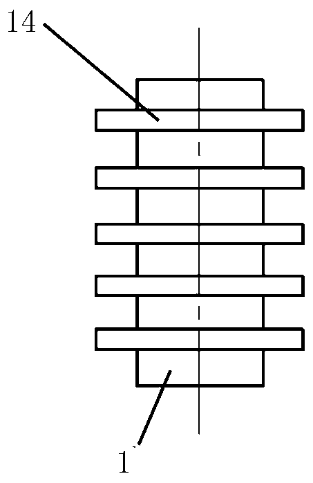
The invention relates to heat exchange systems and particularly relates to an energy-efficient intermediate cooling and heat exchange system for seed decomposition in a seed decomposition process of Bayer-process production of aluminum oxide. A lifting tube is arranged in a seed decomposition tank, a heat exchange sleeve is arranged outside the lifting tube and is provided with a circulating waterfeeding pipe orifice and a circulating water returning pipe orifice, the circulating water feeding pipe orifice is located at the top of the heat exchange sleeve, the circulating water returning pipeorifice is located at the bottom of the heat exchange sleeve and communicates with a cooling tower through a pipe, the cooling tower communicates with a cooling water tank through a pipe, and the cooling water tank communicates with the circulating water feeding pipe orifice through a pipe. The energy-efficient intermediate cooling and heat exchange system has the advantage effects that reinforced heat transferring fins are welded to the lifting tube, and the heat exchange sleeve is arranged outside the lifting tube to form a sleeve heat exchanger. The heat exchange between circulating waterand aluminum hydroxide slurry is achieved during the lifting of the seed decomposition tank, and the decomposition process can be subjected to intermediate cooling without adding a power supply, so that the investment and operating costs are reduced. Compared with the existing intermediate cooling devices needing feeding pumps, the energy saving and consumption reducing advantages are obvious.

Description

technical field [0001] The invention relates to a heat exchange system, in particular to a high-efficiency and energy-saving type intermediate cooling heat exchange system for the alumina seed decomposition process produced by the Bayer method. Background technique [0002] Seed decomposition is a key process in the Bayer process for alumina production. The seed decomposition production process requires intermediate cooling of the aluminum hydroxide slurry. Wide-channel plate heat exchangers or spiral plate heat exchangers are generally used as intermediate cooling equipment. Although plate heat exchangers have the characteristics of high heat transfer efficiency, However, it needs to be equipped with a feeding pump. In addition, the plate heat exchanger needs to be washed with alkali and mother liquor regularly, and it needs to be equipped with a corresponding alkali wash mother liquor flushing process. Therefore, the intermediate cooling of the plate heat exchanger has th...

Claims


Application Information

Patent Timeline
Patent Type & Authority Applications(China)
IPC IPC(8): C01F7/02F28D7/10F28F1/14F28F1/24F28F1/36
CPCC01F7/02F28D7/10F28F1/14F28F1/24F28F1/36Y02P20/10
Inventor 王会兴王剑唐时健宋治林尹德明齐东华
Owner SHENYANG ALUMINIUM MAGNESIUM INSTITUTE
Learn More