
Performance Testing System of Wheel Speed ​​Sensor Based on Simulated Code Wheel

A wheel speed sensor, analog coding technology, applied in the testing/calibration of speed/acceleration/shock measurement equipment, speed/acceleration/shock measurement, instruments, etc. High energy consumption, poor reliability of test results, etc., to eliminate the stability of motor speed, realize online automated testing, and high temperature stability.

Inactive Publication Date: 2016-06-15
SOUTHWEST JIAOTONG UNIV
View PDF5 Cites 0 Cited by
  • Summary
  • Abstract
  • Description
  • Claims
  • Application Information

AI Technical Summary

Problems solved by technology

[0003] However, due to the low stability and precision of the motor speed, the stability and precision of the measurement results of the existing wheel speed sensor performance testing methods or systems are also low.
At the same time, the motor speed is generally 100Hz to 3KHz (converted from the speed to frequency), and it cannot be tested at a low speed of 0Hz to 10KHz or a high speed above 3KHz, even if it can be tested at such a low or high speed. The reliability of the test results is also poor
In addition, due to the influence of thermal expansion and contraction of mechanical parts such as motors in high and low temperature environments, the existing methods can only be tested at room temperature around 20°C, and cannot complete the test of sensors in high and low temperature environments (-40°C). ~+150℃) temperature online continuous test
In addition, the power of the motor is generally in the kilowatt class, which makes the existing test methods or systems consume relatively high energy consumption.

Method used


Image

  • Performance Testing System of Wheel Speed ​​Sensor Based on Simulated Code Wheel
  • Performance Testing System of Wheel Speed ​​Sensor Based on Simulated Code Wheel

Examples


Embodiment Construction

[0020] The present invention will be described in further detail below in conjunction with the accompanying drawings of the specification.

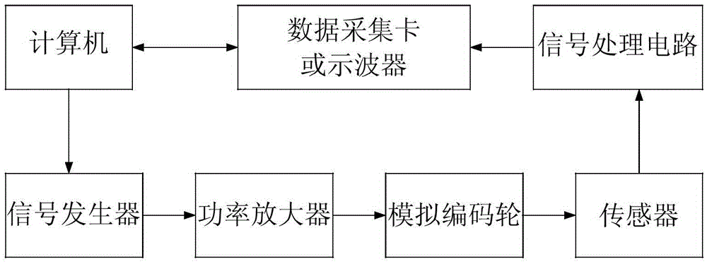
[0021] The invention discloses a wheel speed sensor performance test system based on an analog code wheel, such as figure 1 As shown, it is mainly composed of 7 parts: computer, analog code wheel, power amplifier, signal generator, data acquisition card or oscilloscope, wheel speed sensor and signal processing circuit.

[0022] The computer is the core of the entire testing system, with a friendly human-computer interaction interface, and it is the carrier of the wheel speed sensor testing software. The computer test software includes a test item parameter setting module, a signal generator control module, and a test result processing module (including a test result display module and a test result storage module). Realize the computerized all-digital acquisition, test analysis and test process automation. The computer is connected to the sig...


PUM


Abstract

The invention discloses a wheel speed sensor performance test system based on an analog encoding wheel and belongs to the technical field of electronic product performance testing. The wheel speed sensor performance test system comprises a computer, a signal generator, a power amplifier, the analog encoding wheel, a wheel speed sensor signal processing circuit and a data collecting card or an oscilloscope. The computer controls the signal generator to generate a frequency signal corresponding to the set wheel rotation speed, the frequency signal is amplified by the power amplifier and then is input into the analog encoding wheel, alternating signals generated after an alternating magnetic field generated by the analog encoding wheel is sensed by a wheel speed sensor to be tested are converted into pulse signals by the signal processing circuit, then the pulse signals are converted into frequency test results by the data collecting card or the oscilloscope and are input into the computer, and the computer finally finishes comparison of the test results and evaluation on the performance of the wheel speed sensor. The wheel speed sensor performance test system can achieve high-precision tests within the frequency ranging from 0 to 10 KHz and the temperature ranging from -40 DEG C to 150 DEG C, and has the advantages of saving energy and reducing consumption.

Description

Technical field [0001] The invention belongs to the technical field of electronic product performance testing, and specifically relates to a wheel speed sensor performance testing method and testing system. Background technique [0002] As people’s requirements for automobile safety become higher and higher, advanced ABS (Anti-lock Break System) and ESP (Electronic Stability Program, Electronic Stability Program) technologies have been used more and more. Put forward higher requirements. The wheel speed sensor is an important component of the car control system. The quality of the sensor directly affects whether the effective monitoring and control of other parts of the car can be realized. It is related to the safety of car driving, so it needs to have its performance indicators before the sensor is installed. Carry out effective tests to verify its comprehensive performance. At present, the traditional method of detecting the wheel speed sensor is the wheel speed sensor verif...

Claims


Application Information

Patent Timeline
Patent Type & Authority Patents(China)
IPC IPC(8): G01P21/02
Inventor 田恬张长玲冯斐
Owner SOUTHWEST JIAOTONG UNIV
Learn More