
Device for detecting medical sterile glove for surgery

A detection equipment, a technique for surgery, applied in the direction of detecting the appearance of fluid at the leak point, using liquid/vacuum for liquid tightness measurement, etc., can solve the problems of high labor intensity, low work efficiency, and complicated procedures, etc. Low labor intensity, high work efficiency, and the effect of reducing labor intensity

Active Publication Date: 2018-12-07
山东英科医疗制品有限公司
View PDF10 Cites 7 Cited by
  • Summary
  • Abstract
  • Description
  • Claims
  • Application Information

AI Technical Summary

Problems solved by technology

[0003] In order to solve the above problems, the present invention provides a medical sterile glove testing device for surgery, which can solve the problem that the airtightness of the sterile gloves needs to be manually tested in the production and inspection process of the existing medical sterile gloves, and the gloves need to be checked manually. To inflate, it is necessary to manually expand the opening of the glove, manually insert the air pump into the glove, manually seal the glove during the inflation process, manually sink the inflated glove into the disinfectant for observation, and manually detect the presence of bacterial infection in sterile gloves The procedures for manually wearing sterile clothing are cumbersome, and the sterile gloves that have been manually inspected can only be treated as garbage, wasting resources, high labor intensity and low work efficiency. Automatic air tightness testing of medical sterile gloves can be realized The function of automatic sterility testing gloves does not affect the subsequent use without manual testing, and has the advantages of saving resources, low labor intensity and high work efficiency.

Method used


Image

  • Device for detecting medical sterile glove for surgery
  • Device for detecting medical sterile glove for surgery
  • Device for detecting medical sterile glove for surgery

Examples


Embodiment Construction

[0023] In order to make the technical means, creative features, goals and effects achieved by the present invention easy to understand, the present invention will be further described below in conjunction with specific illustrations.

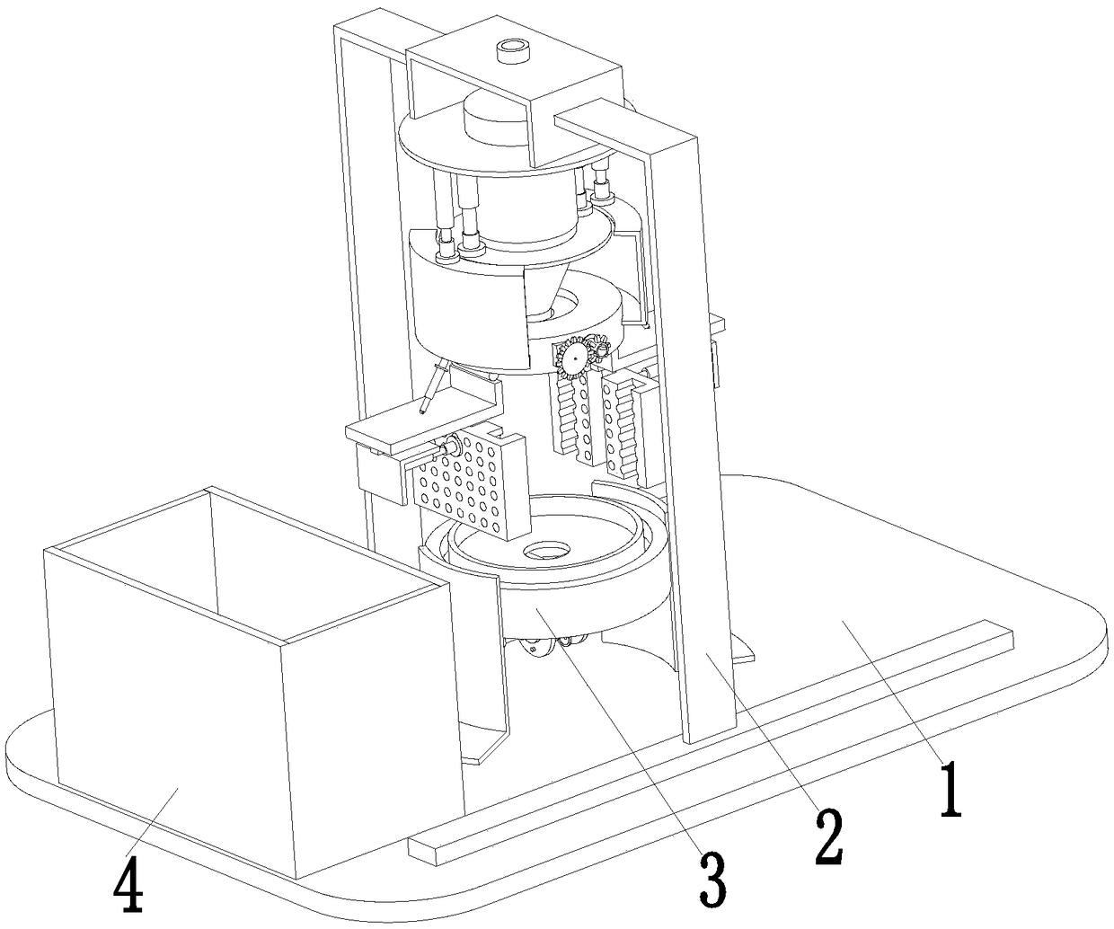
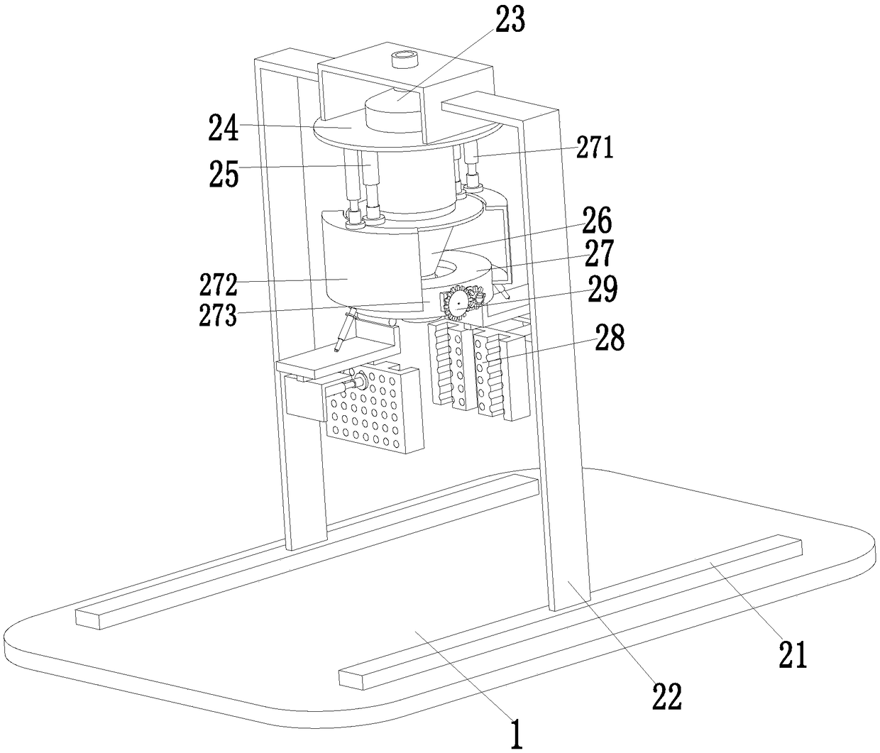
[0024] Such as Figure 1 to Figure 6 As shown, a medical sterile glove testing device for surgery includes a base plate 1 on which a fixed sealing device 2, a tension control device 3 and a test water tank 4 are installed, wherein the tension control device 3 is located at the side of the fixed seal device 2 Directly below, the test water tank 4 is located on the front side of the bottom plate 1, and the test water tank 4 is filled with a special test liquid. The opening and closing control device 3 can control the opening and closing movement of the gloves during work, so that the gloves can be tested with the fixed sealing device 2 Operation, the fixed sealing device 2 can seal the opening of the glove and check the glove with the help of the ...


PUM


Abstract

The invention relates to a device for detecting a medical sterile glove for a surgery. The device comprises a bottom plate, and a fixed sealing device, a tensioning control device and a test water tank are mounted on the bottom plate, wherein the tensioning control device is located directly under the fixed sealing device, and the test water tank is located at the front side of the bottom plate. The manual detection of the airtightness of a sterile glove is needed during the existing production inspection process of the medical sterile glove, the glove needs to be manually inflated, an openingof the glove needs to be manually expanded, an air pump is manually inserted into the glove, the glove during an inflation process is manually sealed, the inflated glove is manually immersed into a disinfectant for observation, the manual detection of the sterile glove has a bacterial infection problem, the procedure of manually wearing sterile clothes is tedious, the manually tested sterile glove can only be treated as garbage, resources are wasted, the labor intensity is large, and the working efficiency is low, the problems can be solved by the device, and the function of the automatic airtightness detection of the medical sterile glove can be achieved.

Description

technical field [0001] The invention relates to the field of medical equipment production equipment, in particular to a detection equipment for surgical medical sterile gloves. Background technique [0002] Sterile gloves are a medical device product that can prevent bacterial infection and are mainly used in operating rooms. Any method of hand washing cannot completely eliminate the bacteria deep in the skin. These bacteria gradually migrate to the surface of the skin and multiply and grow rapidly during the operation. Therefore, you must wear sterile surgical gowns and sterile gloves after washing your hands. Surgery is possible. As a medical device, sterile gloves must be strictly tested during the production process. Air tightness testing is a traditional Chinese medicine link for sterile gloves, but the existing sterile gloves need to manually test the air tightness of sterile gloves during the production inspection process. It is necessary to manually inflate the glo...

Claims


Application Information

Patent Timeline
IPC IPC(8): G01M3/06
CPCG01M3/06
Inventor 潘仲民
Owner 山东英科医疗制品有限公司
Learn More