Synthetic aperture radar antenna stabilization platform integrated test system

A synthetic aperture radar and stable platform technology, applied in radio wave measurement systems, instruments, etc., can solve the problems of cumbersomeness, relatively high requirements for cable shielding characteristics and anti-interference characteristics, and complicated workload of testing personnel, etc., and achieve reduction Effects of difficulty and complexity, increased reliability of accuracy, protection against accidental loss

Pending Publication Date: 2018-12-07
INST OF ELECTRONICS CHINESE ACAD OF SCI
View PDF6 Cites 3 Cited by
  • Summary
  • Abstract
  • Description
  • Claims
  • Application Information

AI Technical Summary

Problems solved by technology

[0005] In the development and production process of the Synthetic Aperture Radar Antenna Platform (SARAP), the traditional testing and calibration methods (that is, the testing and calibration methods based on non-specialized methods) are relatively cumbersome: that is, the functions of the SARAP Modules (PWM control module, power amplifier module, drive motor, gyroscope module, acquisition module, etc.) are calibrated, and the performance of the SARAP machine is also tested and calibrated
The test equipment and cable connection methods required for the calibration of each functional module and the whole machine are different, and the control software used is also different, which brings a complicated workload to the test personnel.
At the same time, since the antenna stabilization platform has a weak current (measurement and control circuit) part and a strong current (motor drive circuit) part, the requirements for cable shielding characteristics and anti-interference characteristics are relatively high during calibration. These factors also increase the test and calibration. difficulty

Method used


Image

  • Synthetic aperture radar antenna stabilization platform integrated test system
  • Synthetic aperture radar antenna stabilization platform integrated test system
  • Synthetic aperture radar antenna stabilization platform integrated test system

Examples


Embodiment Construction

[0044] In order to make the object, technical solution and advantages of the present invention clearer, the present invention will be described in further detail below in conjunction with specific embodiments and with reference to the accompanying drawings.

[0045]It should be noted that, in the drawings or descriptions of the specification, similar or identical parts all use the same figure numbers. Implementations not shown or described in the accompanying drawings are forms known to those of ordinary skill in the art. Additionally, while illustrations of parameters including particular values ​​may be provided herein, it should be understood that the parameters need not be exactly equal to the corresponding values, but rather may approximate the corresponding values ​​within acceptable error margins or design constraints. The directional terms mentioned in the embodiments, such as "upper", "lower", "front", "rear", "left", "right", etc., are only referring to the direction...


PUM


Abstract

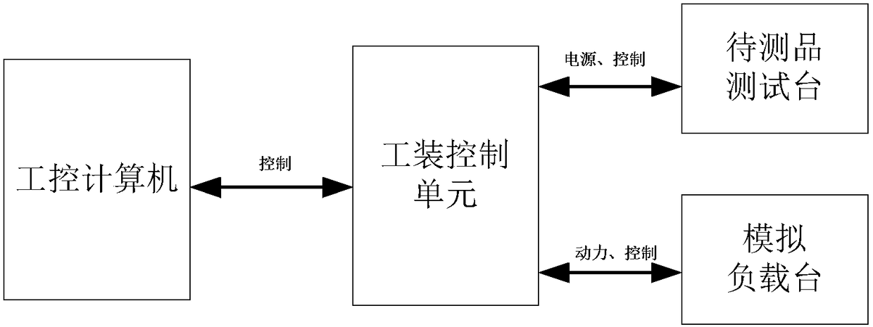
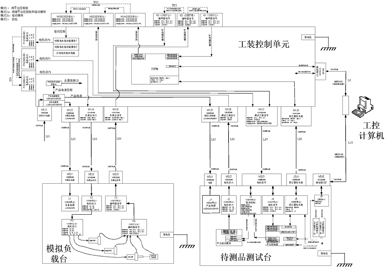
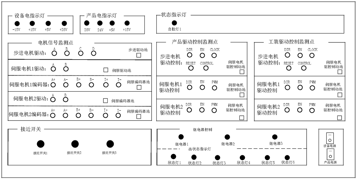
The invention provides a synthetic aperture radar antenna stabilization platform integrated test system, which comprises an industrial control computer, a tooling control unit, a to-be-tested object test platform and a simulated load platform, wherein the industrial control computer is connected with the tooling control unit, is used for controlling the tooling control unit, and is used for acquiring and displaying data transmitted by means of the tooling control unit simultaneously; and the tooling control unit is connected with the to-be-tested object test platform and the simulated load platform, and is used for controlling the to-be-tested object test platform and the simulated load platform, providing electric source and power for the to-be-tested object test platform and the simulated load platform, and acquiring data transmitted by means of the to-be-tested object test platform and the simulated load platform. The synthetic aperture radar antenna stabilization platform integrated test system can prevent accidental loss caused by misconnection of cables, reduces the difficulty and complexity of test calibration, and improves the working efficiency and test precision.

Description

technical field [0001] The invention relates to the technical field of microwave imaging, in particular to a synthetic aperture radar antenna stabilization platform comprehensive test system. Background technique [0002] Synthetic Aperture Radar (SAR) is a high-resolution microwave imaging radar, which has the advantages of all-day, all-weather, and resolution not affected by the height of the carrier platform. SAR plays a very important role in land survey, environment and disaster monitoring, ocean observation, sea surface pollutant monitoring, topographic surveying and mapping, resource exploration, interstellar surveying, etc. in the civilian field. [0003] Antenna stabilization platform is an important part of airborne synthetic aperture radar, which is generally composed of motor, motor drive, gyroscope, mechanical platform and control circuit. Its main function is to follow the inertial navigation parameters while isolating the carrier aircraft and atmospheric dist...

Claims


Application Information

Patent Timeline
Patent Type & Authority Applications(China)
IPC IPC(8): G01S7/40
CPCG01S7/4004
Inventor 洪瀑司广东吕绪明
Owner INST OF ELECTRONICS CHINESE ACAD OF SCI
Why Eureka
Try Eureka