Installation process of deep foundation pit type transmission line tower grounding device

A technology of transmission lines and grounding devices, which is applied in the direction of circuits, lines/collector parts, towers, etc., can solve problems such as inconvenient installation, additional land acquisition costs, and difficult transportation, so as to avoid the influence of grounding resistance, Avoiding difficult excavation and shortening installation time

Inactive Publication Date: 2018-12-07
国网西藏电力有限公司拉萨供电公司 +1
View PDF6 Cites 1 Cited by
  • Summary
  • Abstract
  • Description
  • Claims
  • Application Information

AI Technical Summary

Problems solved by technology

The grounding grid of the existing grounding line usually uses grounding materials such as flat steel, copper, galvanized steel with electroplating technology, copper-clad steel, and graphite modules. In each new grounding grid construction, the four corners of the tower foundation are laid outwards. The quantity used is large and the area occupied is large, resulting in additional compensation for young crops and land requisition costs and huge expenses; at the same time, metal materials are used for grounding. Generally, after 3 to 7 years of operation, it is found that the metal materials are severely corroded, and the grounding resistance exceeds the standard. Second overhaul The problem of high cost of transformation is prominent; moreover, it is difficult to transport metal grounding materials, welding, cutting, anti-corrosion and other processes are required during the construction process, the construction is difficult, the installation is inconvenient, and theft is prone to occur

Method used


Image

  • Installation process of deep foundation pit type transmission line tower grounding device
  • Installation process of deep foundation pit type transmission line tower grounding device
  • Installation process of deep foundation pit type transmission line tower grounding device

Examples


Embodiment Construction

[0022] The present invention will be described in further detail below in conjunction with the accompanying drawings.

[0023] An installation process of a grounding device for a pole tower of a deep foundation pit type transmission line, comprising the following steps:

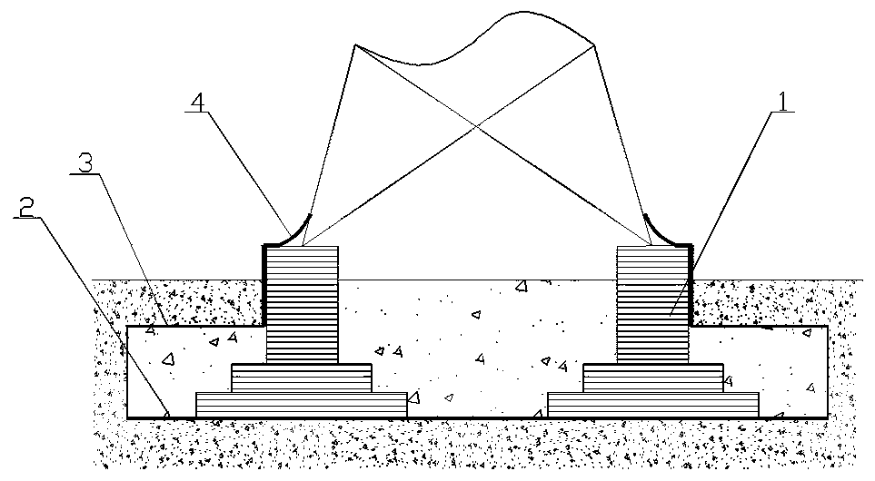
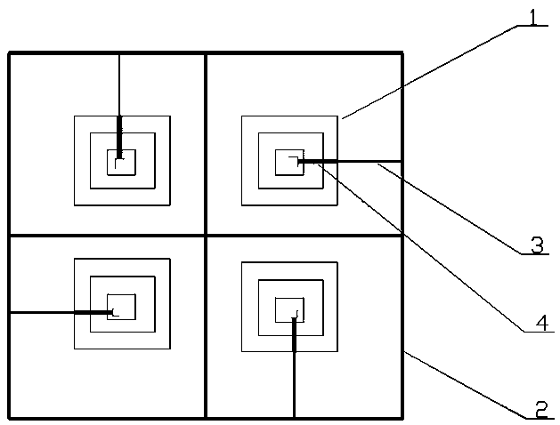
[0024] Step 1. After the excavation of the deep foundation pit is completed, build four transmission line tower foundations 1 in the deep foundation pit, and clean up the sundries in the deep foundation pit when the transmission line tower foundation 1 is completed and the deep foundation pit has not been backfilled , and ensure that the bottom of the deep foundation pit is flat and free of exposed hard objects, and then lay graphite grounding strips 2 around the foundations 1 of the four transmission line towers at the bottom of the deep foundation pit to form a box-shaped structure, and each transmission line tower One side of foundation 1 reserves the joint of graphite grounding belt 2;

[0025] Step 2: U...


PUM


Abstract

The invention relates to a technical process of a deep foundation pit type transmission line tower grounding construction device. When transmission line tower foundations are being established and a foundation pit is not backfilled, a graphite grounding strip is used as a grounding material, a section of the graphite grounding strip is used as a leading up wire, the head end of each leading up wire is connected with the graphite grounding strip, and the tail ends or the leading up wires are connected with grounding downleads preset on the top surfaces of the transmission line tower foundationsseparately, thereby completing the installation of the grounding devices. The graphite grounding strip is corrosion-resistant, non-rusting and easy to lay, the grounding resistance is stable, the installation process is especially applicable to places with acid and alkaline soils, difficult construction and high resistivity, the secondary young crop compensation fee and the land acquisition fee brought by secondary excavation are avoided, especially in regions with high compensation fees of grasslands, agricultural and forestry land and the like, and non-metallic fixtures are adopted for connecting the graphite grounding strip and leading up wires, thus the installation process is faster and more convenient.

Description

technical field [0001] The invention relates to the technical field of transmission line pole tower grounding, in particular to an installation process of a deep foundation pit type power transmission line pole tower grounding device. Background technique [0002] The reliability of the grounding device is the key work to prevent lightning tripping events and protect the safe operation of transmission lines. The grounding grid of the existing grounding line usually uses grounding materials such as flat steel, copper, galvanized steel with electroplating technology, copper-clad steel, and graphite modules. In each new grounding grid construction, the four corners of the tower foundation are laid outwards. The quantity used is large and the area occupied is large, resulting in additional compensation for young crops and land requisition costs and huge expenses; at the same time, metal materials are used for grounding. Generally, after 3 to 7 years of operation, it is found tha...

Claims


Application Information

Patent Timeline
Patent Type & Authority Applications(China)
IPC IPC(8): H01R4/66H01R43/00E04H12/34
CPCH01R4/66E04H12/347H01R43/00
Inventor 陈四甫达娃伦珠潘志远陶魁朱彤邵明恒杨翔唐芳胡松江务孔永陈彦青张国锋
Owner 国网西藏电力有限公司拉萨供电公司
Why Eureka
Try Eureka