Power supply detecting and switching device for electric energy meter

A power detection and switching device technology, which is applied to circuit devices, emergency power arrangements, electrical components, etc., can solve the problems of switching power supply damage, bursting, and high voltage in the transformer area, and achieve the effect of reducing power consumption

Pending Publication Date: 2018-12-07
杭州乾程弘泰电力科技有限公司
View PDF4 Cites 3 Cited by
  • Summary
  • Abstract
  • Description
  • Claims
  • Application Information

AI Technical Summary

Problems solved by technology

[0004] The purpose of the present invention is to overcome the shortcomings of the prior art, to design a power supply detection and switching device for electric energy meters, and to solve the problem

Method used


Image

  • Power supply detecting and switching device for electric energy meter
  • Power supply detecting and switching device for electric energy meter
  • Power supply detecting and switching device for electric energy meter

Examples


Embodiment

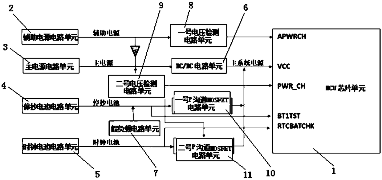
[0024] The main structure of the electric energy meter power detection and switching device involved in this embodiment includes an MCU (micro control unit) chip unit 1, an auxiliary power supply circuit unit 2, a main power supply circuit unit 3, a stop reading battery circuit unit 4, and a clock battery circuit unit 5. DC / DC circuit unit 6, dummy load circuit unit 7, No. 1 voltage detection circuit unit 8, No. 2 voltage detection circuit unit 9, No. 1 P-channel MOSFET circuit unit 10 and No. 2 P-channel MOSFET circuit unit 11 ; MCU chip unit 1 includes APWRCH end, VCC end, PWR-CH end, BT1TST end and RTCBATCHK end, and auxiliary power supply circuit unit 2 is connected to the APWRCH end of MCU chip unit 1 after the auxiliary power supply circuit unit 2 is connected in series with No. 1 voltage detection circuit unit 8; The circuit unit 3 has two branches, one of which is connected to the VCC terminal of the MCU chip unit 1 after being connected in series with the DC / DC circuit...


PUM


Abstract

The invention belongs to the technical field of switching power supply protection, and relates to a power supply detecting and switching device for an electric energy meter. The power supply detectingand switching device comprises an MCU chip unit, an auxiliary power circuit unit, a main power circuit unit, a power-off meter-reading battery circuit unit, a clock battery circuit unit, a DC/DC circuit unit, a dummy load circuit unit, a first voltage detecting circuit unit, a second voltage detecting circuit unit, a first P-channel MOSFET circuit unit, and a second P-channel MOSFET circuit unit.A power supply detects whether the first voltage detecting circuit unit, the second voltage detecting circuit unit and the DC/DC circuit unit are powered on. The MCU chip unit detects the levels of the first voltage detecting circuit unit, the second voltage detecting circuit unit and the DC/DC circuit unit. When the main power circuit unit is powered off, the power supply automatically switchesto the power-off meter-reading battery circuit unit, and the MCU chip unit is in a low-power mode. When the power-off meter-reading battery circuit unit has no power, the power supply automatically switches to the clock battery circuit unit for power supply.

Description

Technical field: [0001] The invention belongs to the technical field of switching power supply protection, and relates to a power supply detection and switching device for an electric energy meter, which provides an idea for a switching power supply scheme with wide input and high reliability performance, and is suitable for three-phase meters and terminal occasions where the input voltage is too high in the station area . Background technique: [0002] The power supply is a device that provides power to electronic equipment, also known as a power supply. The size of the power supply, the common power supply is a dry battery (direct current) and a household 110V-220V AC power supply. Whether the current and voltage are stable will directly affect the performance of electronic equipment. In order to improve the working performance and service life, it is necessary to detect and switch the power supply. A charging source detection switching device disclosed in Chinese patent ...

Claims


Application Information

Patent Timeline
IPC IPC(8): H02J9/04
CPCH02J9/06Y02B70/30Y04S20/20
Inventor 张荣升
Owner 杭州乾程弘泰电力科技有限公司
Why Eureka
Try Eureka