
A temperature control fixture and method for testing the influence of temperature on lens focal length

A lens and focal length technology, applied in TV, electrical components, image communication, etc., can solve the problems of poor application effect, inability to understand and control lens modules, large quality differences, etc., to achieve convenient production, flexible and convenient operation, and manufacturing. and the effect of low application cost

Active Publication Date: 2020-08-14
YUYAO SUNNY OPTICAL INTELLIGENCE TECH CO LTD
View PDF7 Cites 0 Cited by
  • Summary
  • Abstract
  • Description
  • Claims
  • Application Information

AI Technical Summary

Problems solved by technology

However, in the actual application process, the lens modules shipped out of the factory after the above-mentioned resolution test will still have good test results and normal quality in the production process, but the actual application effect of the customer is poor, or there is a big difference in quality between the first start and after working for a period of time. In addition, the above-mentioned test system can only test the finished camera module, and cannot help production and R&D personnel understand and control the specific conditions of individual lenses in the lens module affected by temperature during the production, design and development process

Method used


Image

  • A temperature control fixture and method for testing the influence of temperature on lens focal length
  • A temperature control fixture and method for testing the influence of temperature on lens focal length
  • A temperature control fixture and method for testing the influence of temperature on lens focal length

Examples


Embodiment 1

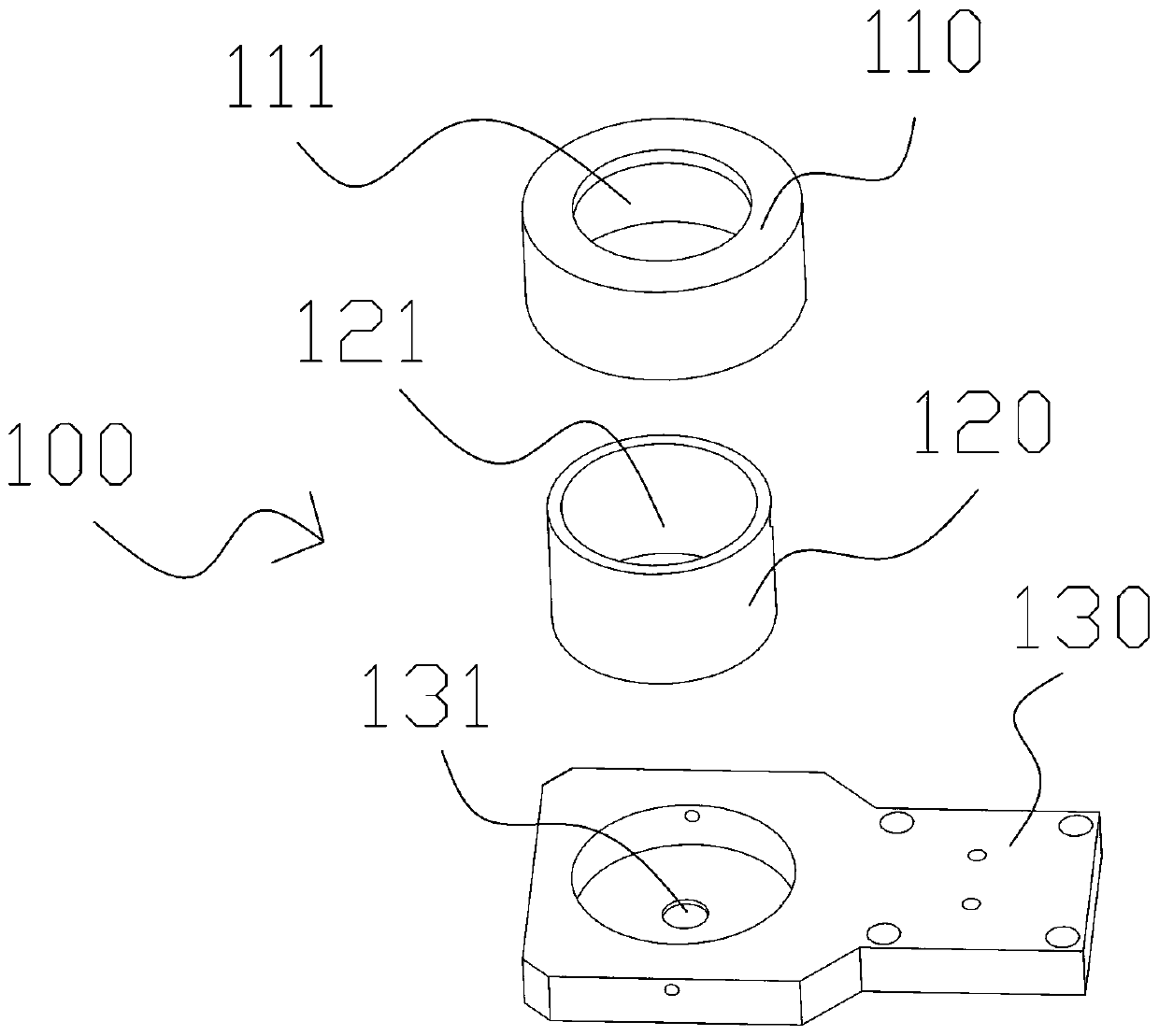
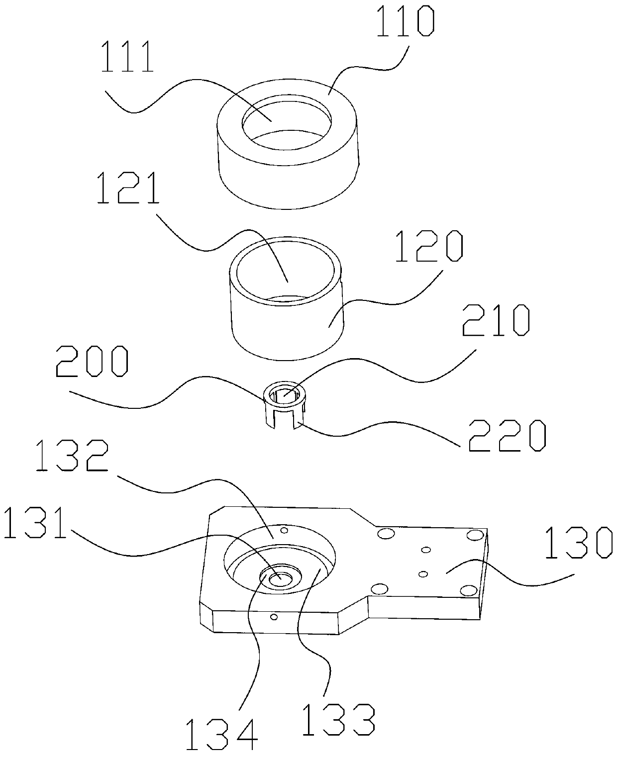
[0043] Such as figure 1 As shown, this embodiment provides a temperature control jig for testing the influence of temperature on the focal length of the lens, including a temperature control regulator and a heater 100. The heater 100 includes a protective cover 110, a heating body 120, and a heat insulation base. 130, the protective cover 110 is provided outside the heating body 120, the protective cover 110 has an inlet port 111, the heating body 120 has a hollow portion 121, the heat insulation base 130 has a light hole 131, the The inlet port 111, the hollow portion 121, and the light through hole 131 are in communication with each other. The heating body 120 is electrically connected to the temperature control regulator, and the temperature control regulator is used to change the temperature of the heating body 120.

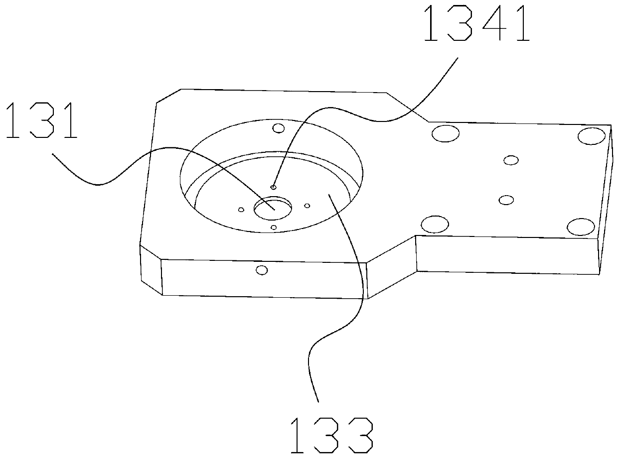
[0044] Specifically, the heating body 120 is placed on the heat-insulating base 130, the hollow part 121 is opposite to the light-passing hole 131, that is, the ...

Embodiment 2

[0058] This embodiment provides a method for testing the influence of temperature on the focal length of a lens, and the used testing device includes: an optical focal length adjustment device 3, an optical resolution test device, and the temperature control fixture described in embodiment 1, such as Figure 5 As shown, the optical focus adjustment device 3 includes a first fine-tuning platform 31 and a second fine-tuning platform 32, and the method includes the following steps:

[0059] Put the lens to be tested into the heater 100 from the inlet port 111, fix the heater 100 on the first fine-tuning platform 31, and place the photosensitive chip on the second fine-tuning platform 32 , Placing the optical focal length adjustment device 3 on a testing machine platform of the optical resolution testing device;


PUM


Abstract

The invention relates to the technical field of thermal stability of optical systems and discloses a temperature control tool and method used for test of effects on the focal length of a lens imposedby temperature. The temperature control tool comprises a temperature control adjuster and a heater. The heater comprises a protection cover, a heating body and a heat isolation base. The protection cover is arranged out of the heating body and comprises an entrance port. The heating body comprises a hollow part. The heat isolation base comprises a light passing hole. The entrance port, the hollowpart and the light passing hole communicate with each other. The heating body is electrically connected with the temperature control adjuster. The method comprises steps of adjusting the distance between the lens and a light sensing chip in a temperature change process to acquire a test method of images with the same resolution; and quite directly and clearly displaying focal length effects on thelens imposed by temperature change. According to the invention, the tool is simple in structure, small in size, low in manufacturing and application cost and capable of helping production and research staff to test effects on the focal lens of the lens imposed by the temperature change in a production or research and development design process, and design and type-selection data support is provided for the preliminary stage of the design.

Description

Technical field [0001] The invention relates to the technical field of optical system thermal stability, in particular to a temperature control jig and method for testing the influence of temperature on lens focal length. Background technique [0002] The destructive effect of the various components of the optical system on the image quality affected by the temperature field of the structure and the surrounding environment has long been a consensus. For many years, technicians from various countries have been committed to developing and improving the level of structural design and thermal design to ensure the optical system’s performance. performance. [0003] The development of aerial photography and panoramic technology has prompted the pursuit of higher-quality precision and clarity for optical systems. The fixed focus module is widely used in aerial cameras and panoramic cameras due to its fast focusing speed and stable image quality. The resolution of this type of module is e...

Claims


Application Information

Patent Timeline
Patent Type & Authority Patents(China)
IPC IPC(8): H04N17/00
CPCH04N17/002
Inventor 罗孟杰洪铁迪潘周权
Owner YUYAO SUNNY OPTICAL INTELLIGENCE TECH CO LTD
Learn More