Glue dispensing method and device

A technology of glue dispensing and glue dispensing machine, which is applied to devices and coatings that apply liquid to the surface, which can solve problems such as pollution, glue overflow and residual glue.

Pending Publication Date: 2018-12-11
WUXI LEAD INTELLIGENT EQUIP CO LTD
View PDF7 Cites 1 Cited by
  • Summary
  • Abstract
  • Description
  • Claims
  • Application Information

AI Technical Summary

Problems solved by technology

[0005] The first purpose of the present invention is to provide a glue dispensing method to solve the technical problems existing in the prior art that after the completion of glue dispensing for cell edge sealing, the glue thread is likely to cause overflowing glue residue and easily cause glue pollution
[0006] The second object of the present invention is to provide a glue dispensing device to solve the technical problems existing in the prior art that after glue dispensing is completed for cell edge sealing, the glue thread is likely to cause overflow glue residue and glue pollution.

Method used


Image

  • Glue dispensing method and device
  • Glue dispensing method and device
  • Glue dispensing method and device

Examples


Embodiment 1

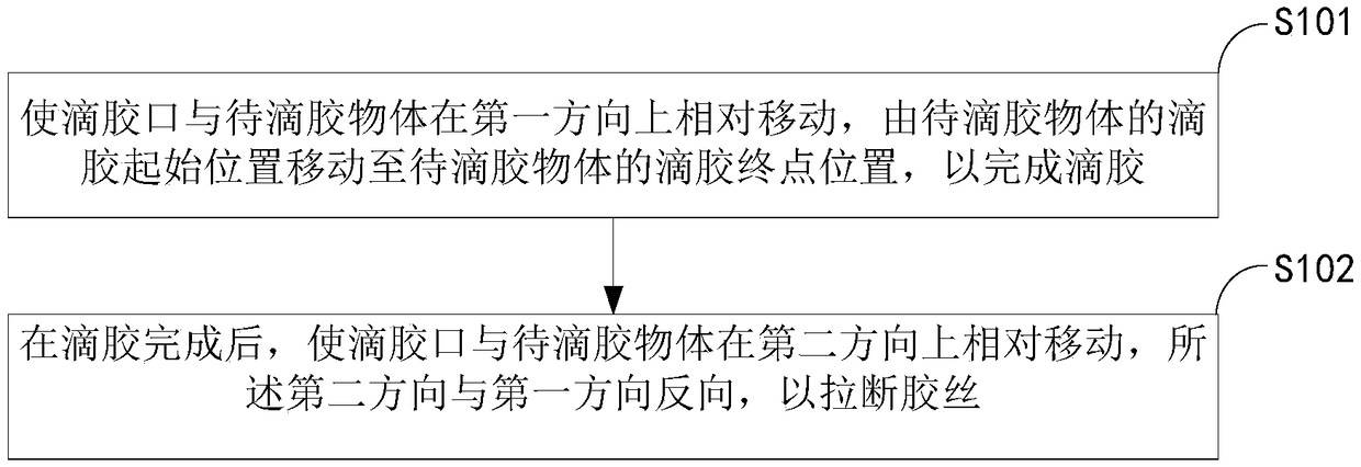
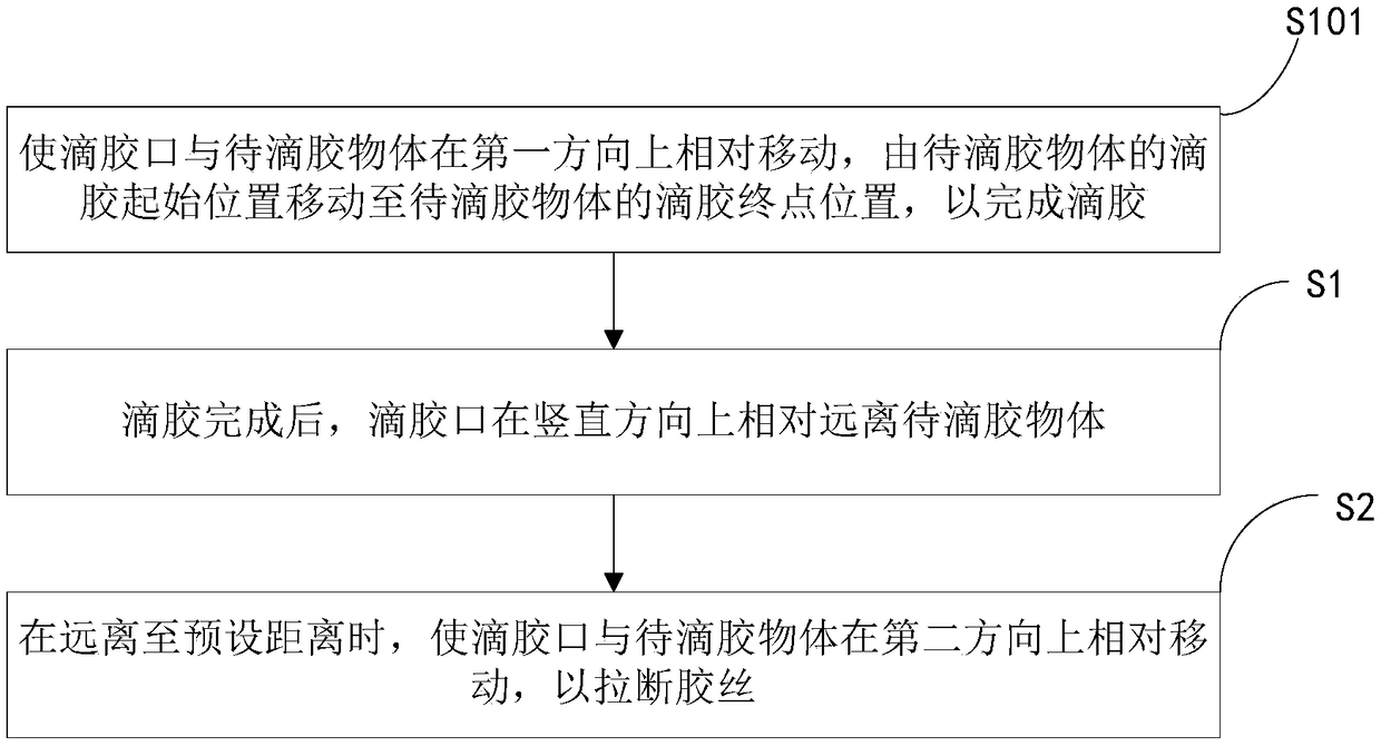
[0067] see Figure 2 to Figure 3 As shown, the present embodiment provides a kind of glue dropping method, and described method comprises:

[0068] Step S101: Make the dispensing port and the object to be dispensed relatively move in a first direction, from the dispensing start position of the dispensing object to the dispensing end position of the dispensing object, so as to complete the dispensing.

[0069] It can be understood that this step can be realized in two ways: the object to be dispensed is stationary, and the relative movement between the dispense port and the object to be dispensed is realized by driving the dispense port to move; Drive the object to be dispensed to move, and realize the relative movement between the dispenser port and the object to be dispensed.

[0070] In this step, the relative moving speed between the glue dispensing port and the object to be dispensed is not greater than 200mm / s, and the dispensing speed of the glue dispensing port is 90mm...

Embodiment 2

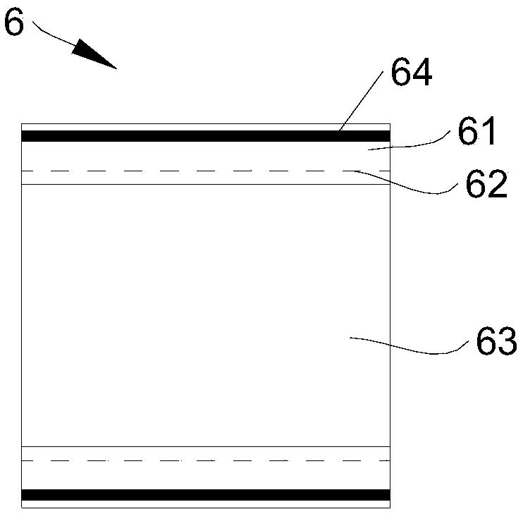
[0086] Such as Figure 4-6 As shown, this embodiment provides a glue dispensing device, which can realize the glue dispensing method described in Embodiment 1. For the convenience of description, this embodiment takes the realization of the edge sealing of the battery cell as an example for illustration.

[0087] The glue dispensing device in this embodiment includes a glue dispensing machine, a first driving mechanism 3 , a third driving mechanism 4 , a second driving mechanism 5 and an angle adjusting mechanism 2 .

[0088] Wherein, the glue dispensing machine 1 is provided with a glue dispensing port, and the glue dispensing machine 1 is provided with a heat shield 11 .

[0089] The angle adjustment mechanism 2 can realize the adjustment of the glue dispensing port of the dispensing machine; the first driving mechanism 3 can drive the dispensing machine to move along the first direction or the second direction, and the second driving mechanism 5 can drive the dispensing ma...


PUM


Abstract

The invention relates to the technical field of battery cell edge sealing glue dispensing, and discloses a glue dispensing method and device. The glue dispensing method specifically comprises the following steps that a glue dispensing port and an object to be subjected to glue dispersing are enabled to move relative to each other in the first direction and are enabled to move from the initial position of glue dispensing of the object to be subjected to glue dispersing to the final position of glue dispensing of the object to be subjected to glue dispersing so as to complete glue dispensing; and after glue dispensing is completed, the glue dispersing port and the object to be subjected to glue dispersing are enabled to move relative to each other in the second direction, and the second direction is opposite to the first direction so as to pull and break glue wires. According to the glue dispensing method and device, glue overflow and glue residues cannot be generated in the glue wire pulling and breaking process, in addition, glue droplets can drop onto glue tape when the glue wires are pulled and broken, and pollution to other equipment caused by glue can be further avoided.

Description

technical field [0001] The invention relates to the technical field of glue dispensing for edge sealing of battery cells, in particular to a glue dispensing method and device. Background technique [0002] The battery cell is the core component of the battery. During the production process of the battery cell, the battery body should be packaged to avoid leakage of the electrolyte. Currently, the commonly used packaging method is to glue the edge of the battery cell. . [0003] Specifically, such as figure 1 Shown is the cell structure to be edge-sealed. The cell 6 includes a cell body 63 and a cell edge 61 arranged on the edge of the cell body 63. The cell edge 61 is parallel to the side of the cell body 63. Creases 62 are provided. At present, the general process of dispensing glue is as follows: the first end of the cell edge 61 away from the battery body 63 is aligned with the glue dispensing port of the glue dispensing device, and then the cell body 63 moves relative...

Claims


Application Information

Patent Timeline
Patent Type & Authority Applications(China)
IPC IPC(8): B05C5/02B05C13/02B05C11/00B05D1/26
CPCB05C5/02B05C11/00B05C13/02B05D1/26
Inventor 不公告发明人
Owner WUXI LEAD INTELLIGENT EQUIP CO LTD
Why Eureka
Try Eureka