Double-face groove profile cutting blade

A technology of cutting inserts and double-sided grooves, which is applied in turning equipment, accessories of tool holders, and tools used in lathes, etc., can solve the problem that built-up edge cannot be effectively suppressed, the sharpness and stability of a single blade, and the processing Surface chip plastic deformation and other problems, to avoid work hardening and plastic deformation of chips, prevent damage, reduce abnormal wear

Active Publication Date: 2018-12-11
OKE PRECISION CUTTING TOOLS CO LTD
View PDF9 Cites 1 Cited by
  • Summary
  • Abstract
  • Description
  • Claims
  • Application Information

AI Technical Summary

Problems solved by technology

[0007] The technical problem to be solved by the present invention is that in the prior art, the sharpness of the blade and the overall stability of the blade are not fully considered, and the single pursuit of the sharpness of the blade or the overall stability of the blade results in the processing of the surface Abnormal wear due to excessive work hardening and plastic...

Method used


Image

  • Double-face groove profile cutting blade
  • Double-face groove profile cutting blade
  • Double-face groove profile cutting blade

Examples


Embodiment 1

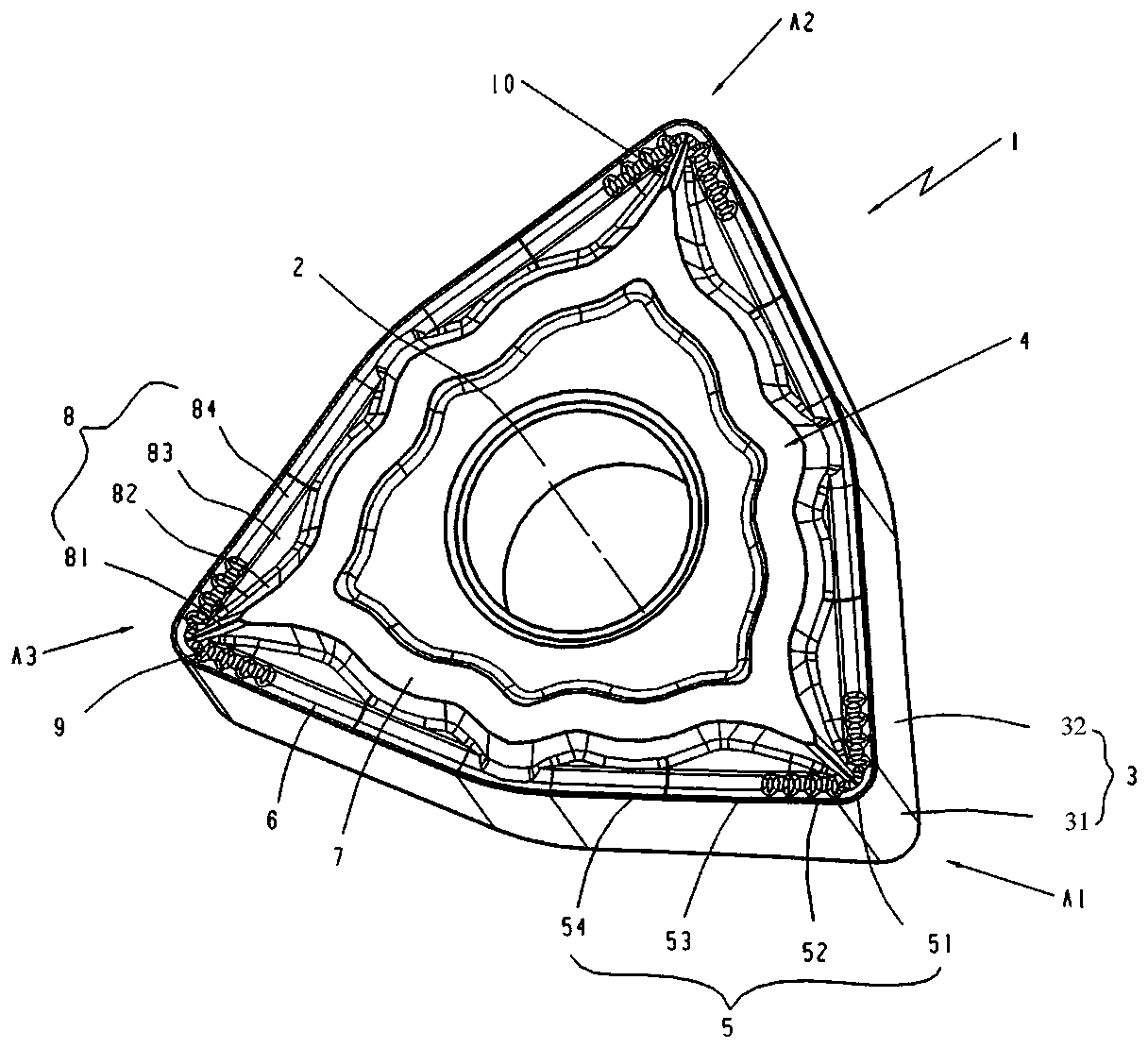
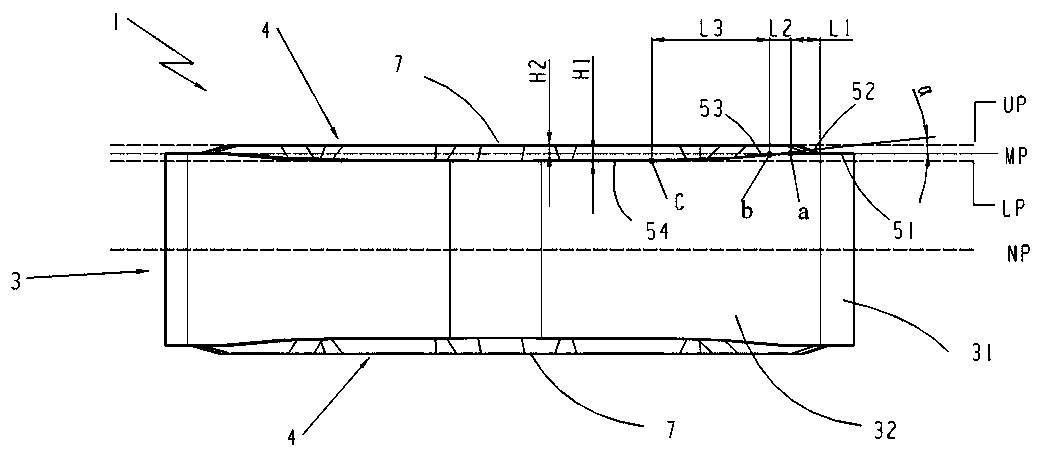
[0033] Such as figure 1 As shown, a double-sided groove type cutting insert, the above-mentioned insert body 1 is a geometric structure with a polygonal up-and-down symmetrical arrangement, the insert body 1 is provided with a insert positioning hole 3 located at the geometric center, and the above-mentioned insert body 1 consists of an upper end surface, The lower end surface 4, a plurality of side surfaces 32 connecting the upper surface and the lower surface 4, and the arc side surface 31 between two adjacent side surfaces 32, in this embodiment, the blade body 1 is approximately equilateral Geometric structure of equiangular hexagonal body symmetrically set up and down. Both the upper end surface and the lower end surface 4 are provided with a support surface 7 along the edge of the chip breaker 10 and between the positioning hole 2. The support surface 7 is the highest plane of the upper end surface 4 and is close to the side of the cutting guide surface 8. The second cu...


PUM


Abstract

The invention relates to the technical field of metal cutting, and discloses a double-face groove profile cutting blade. A blade body is of a geometric structure, wherein the geometric structure is provided with a polygon and is symmetric up and down. A positioning hole is formed in the geometric center. The blade body is composed of an upper end face, a lower end face, a plurality of side surfaces and an arc side face located between every two adjacent side surfaces, and the upper end face and the lower end face are provided with supporting surfaces between the edges of scrap cutting tables and the positioning hole. The top corner of the blade is provided with no fewer than one cutting unit part, and each cutting unit part is composed of a cutting edge, the corresponding scrap cutting table and a scrap cutting guiding protruding part, wherein the scrap cutting table is composed of a front blade face and a plurality of cutting guiding faces, the scrap cutting guiding protruding part isarranged at the top corner of the cutting unit part, and the cutting edge is composed of an arc cutting edge body, a main cutting edge body, a transition cutting edge body and an auxiliary cutting edge body. Through the blade, the sharpness and stability of the cutting edges are improved, scrap cutting and discharging are smooth, blade abrasion is reduced, and the phenomenon of built-up edges iseffectively restrained.

Description

technical field [0001] The invention relates to the technical field of metal cutting, and more specifically, to a double-sided groove cutting insert. Background technique [0002] Materials such as stainless steel and nickel-based alloys have high alloy element content and strong plastic deformation ability. Usually, the cutting force is large during turning, which generates a lot of heat, which makes the temperature of the tool rise sharply, resulting in the deformation of the tool material. The strength decreases, which increases the wear of the tool due to high temperature oxidation; [0003] At the same time, stainless steel often causes work hardening due to plastic deformation during the processing process, which causes the chips in the cutting process to become tough. During the processing process, if the flow direction and discharge of the chips are not properly guided, this will lead to uncontrolled chip flow. It will cause scratches on the processed surface, and e...

Claims


Application Information

Patent Timeline
IPC IPC(8): B23B27/22
CPCB23B27/22
Inventor 谢清亮李树强袁美和唐文清
Owner OKE PRECISION CUTTING TOOLS CO LTD
Why Eureka
Try Eureka