
Welding gun clamping device for double TIG high-speed welding process

A welding process and clamping device technology are applied in the field of adjustment of the position and attitude of the welding torch during the double TIG high-speed welding of stainless steel thin-walled tubes, achieving the effects of strong practicability, easy promotion and error reduction.

Active Publication Date: 2018-12-11
SHANDONG UNIV
View PDF3 Cites 0 Cited by
  • Summary
  • Abstract
  • Description
  • Claims
  • Application Information

AI Technical Summary

Problems solved by technology

In the actual welding production of stainless steel thin-walled pipes, it is difficult for people to adjust the position and posture of the main and auxiliary welding torches more accurately, and the position and posture of the welding torch have a great influence on the quality of the weld seam. Therefore, a design is made. The torch clamping device suitable for the double TIG welding process is of great significance to the actual welding production of stainless steel thin-walled pipes and the promotion and application of the double TIG welding process

Method used


Image

  • Welding gun clamping device for double TIG high-speed welding process
  • Welding gun clamping device for double TIG high-speed welding process

Examples


Embodiment 1

[0036] Example 1: For specifications of The 304 stainless steel pipe adopts double TIG welding process for welding production. Through the process test, a good weld shape can be obtained, and the welding speed can reach 3.0m / min. Among them, the main current is 293A, the auxiliary current is 150A, and the main arc is argon. The flow rate is 10L / min, the auxiliary arc argon gas flow rate is 15L / min, the inclination angle of the main tungsten pole is 84°, the inclination angle of the auxiliary tungsten pole is 80°, the arc length of the main arc is 1.2mm, and the arc length of the auxiliary arc is 2.5mm. The tip angle of the pole is 30°, the tip angle of the auxiliary tungsten pole is 60°, the diameter of the tungsten pole is 3.2mm, and the distance between the tungsten poles is 20mm. On the basis of the combination of the above optimal parameters, through measurement, the outer diameter of the ceramic nozzle is 18mm, the center distance of the through hole of the jacket is 23.5...

Embodiment 2

[0037] Example 2: For specifications of The 304 stainless steel pipe adopts double TIG welding process for welding production. Through the process test, a good weld shape can be obtained, and the welding speed can reach 3.0m / min. Among them, the main current is 180A, the auxiliary current is 160A, and the main arc is argon The flow rate is 10L / min, the auxiliary arc argon gas flow rate is 15L / min, the inclination angle of the main tungsten pole is 86°, the inclination angle of the auxiliary tungsten pole is 80°, the arc length of the main arc is 2mm, the arc length of the auxiliary arc is 3mm, the main tungsten pole tip The angle is 50°, the tip angle of the auxiliary tungsten pole is 60°, the diameter of the tungsten pole is 3.2mm, and the distance between the tungsten poles is 16.5mm. Based on the combination of the above optimal parameters, through measurement, the outer diameter of the ceramic nozzle is 18mm, the center distance of the through hole of the jacket is 20.5mm...

Embodiment 3

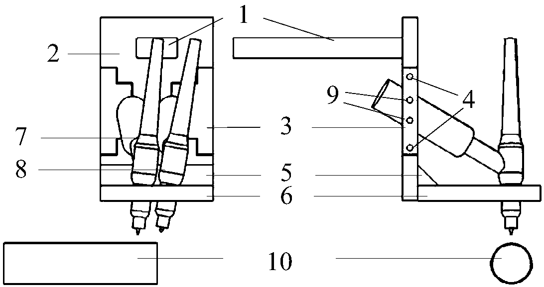
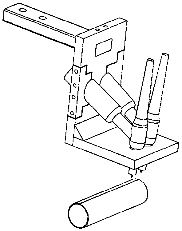
[0039] A welding torch clamping device for a double TIG high-efficiency welding process, comprising: a right-angle bracket, two through holes for fixing the nozzle of the welding torch are arranged on the horizontal surface of the right-angle bracket, and a handle clamp is arranged on the vertical surface of the right-angle bracket Holding plate 2 and clamping plate buckle plate 3, after the handle clamping plate 2 and clamping plate buckle plate 3 are closed, two holes for fixing the handles of welding torches 7 and 8 are formed, and the handle clamping plate 2 is also provided with The support 1, the support 1 and the horizontal plane of the right-angle bracket are respectively located on both sides of the vertical plane of the right-angle bracket.

[0040] The fastening device 4 is a threaded hole arranged on the side of the buckle plate of the clamping plate 2 .

[0041] A jacket 6 matching the nozzle of the welding torch is arranged on the through hole.

[0042] The abov...


PUM

PropertyMeasurementUnit
Outer diameteraaaaaaaaaa

Abstract

The invention provides a welding gun clamping device for a double TIG efficient welding process. The welding gun clamping device comprises a right-angle bracket; the horizontal surface of the right-angle bracket is provided with two through holes for fixing welding gun nozzles; the vertical surface of the right-angle bracket is provided with a handle clamping plate and a clamping plate buckling plate; two holes for fixing welding gun handles are formed after the handle clamping plate and the clamping plate buckling plate are closed; the handle clamping plate is further provided with a supporting member; and the horizontal surface of the supporting member and the horizontal surface of the right-angle bracket are located on the two sides of the vertical surface of the right-angle bracket correspondingly. Through the device, the optimal positions and postures of two welding guns corresponding to given wall thicknesses can be fixed, by quickly replacing welding gun jackets, the optimal positions and postures of the two welding guns corresponding to the different wall thicknesses are fixed, therefore, errors generated during adjustment of the positions and postures of the welding guns can be effectively reduced, the adjustment process of high-speed welding production parameters such as the relative position of the double TIG welding guns is greatly simplified, and the double TIG high-speed welding process is simpler and more convenient.

Description

technical field [0001] The invention belongs to the field of welding, and in particular relates to the adjustment of the position and posture of a welding torch during double TIG high-speed welding of stainless steel thin-walled pipes. Background technique [0002] Welding technology is the key technology for the production of stainless steel thin-walled tubes. Tungsteninert gas (TIG) welding has the characteristics of stable arc, low cost, smooth and beautiful weld seam, and high welding quality. It is especially suitable for thin plate welding. For the welding production of pipes (wall thickness ≤ 3mm), TIG welding has become one of the most commonly used welding methods. In the traditional single TIG welding process, due to the limited current-carrying capacity of the tungsten electrode, the arc power is restricted, resulting in shallow weld penetration and low welding speed, which seriously limits the production efficiency of stainless steel thin tubes. If single TIG hi...

Claims


Application Information

Patent Timeline
IPC IPC(8): B23K9/28
CPCB23K9/287
Inventor 秦国梁江海红王世路冯超
Owner SHANDONG UNIV
Learn More