
An automatic loading and unloading system suitable for functional testing equipment
A technology of automatic loading and unloading and functional testing, which is applied to the stacking of objects, mechanical conveyors, conveyor objects, etc., and can solve the problems of large footprint of functional testing equipment, positioning errors of mechanical arms for products, and small space utilization. problem, to achieve the effect of facilitating the positioning and grabbing of the tray and the product, ensuring the coordination and adaptability of the action, and increasing the stability and smoothness
- Summary
- Abstract
- Description
- Claims
- Application Information
AI Technical Summary
Problems solved by technology
Method used
Image

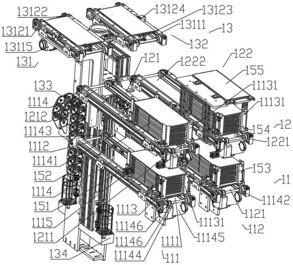
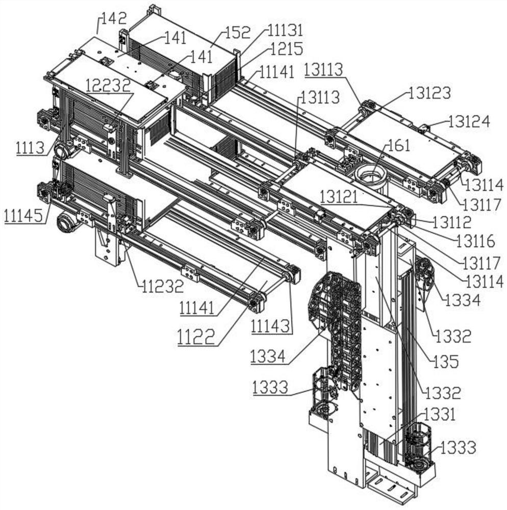
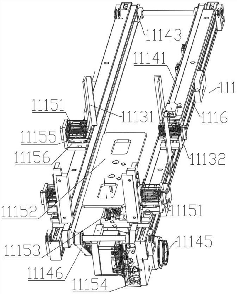
Examples
Embodiment Construction
[0055] In order to more clearly illustrate the embodiments of the present invention or the technical solutions in the prior art, the specific implementation manners of the present invention will be described below with reference to the accompanying drawings. Obviously, the accompanying drawings in the following description are only some embodiments of the present invention, and those skilled in the art can obtain other accompanying drawings based on these drawings and obtain other implementations.
[0056]In order to make the drawing concise, the parts related to the present invention are only schematically shown in each drawing, and they do not represent the actual structure of the product. In addition, to make the drawings concise and easy to understand, in some drawings, only one of the components having the same structure or function is schematically shown, or only one of them is marked. Herein, "a" not only means "only one", but also means "more than one". In this artic...
PUM
 Abstract
Description
Claims
Application Information