Ship hoisting device

A technology for hoisting devices and ships, which is applied in hoisting devices, portable hoisting devices, cranes, etc., and can solve problems such as inconvenient use of the device, unrestricted range of movement of the coil sleeve, and inability to meet the hoisting needs of ships, etc.

Inactive Publication Date: 2018-12-11
芜湖籁余新能源科技有限公司
View PDF9 Cites 6 Cited by
  • Summary
  • Abstract
  • Description
  • Claims
  • Application Information

AI Technical Summary

Problems solved by technology

[0002] After the hull structure is pre-assembled to form sections or general sections, it needs to be transported to the berth with a hoisting device and then assembled and welded to form the entire hull, that is, the general assembly of the hull, also known as large closing. On the basis of assembly and welding, general section assembly and welding, outfitting and painting, the overall assembly and welding of the ship and the process of outfitting and painting are completed on the berth, which is directly related to ensuring the quality of ship construction and shortening the construction period of ships. , when the traditional hoisting device is in use, when the ship is hoisted with the traction rope, the range of motion of the coil sleeve is not limited, which brings inconvenience to the use of the device. At the same time, the position of the hoisting parts of the device is fixed, which cannot meet the requirements Hoisting requirements of ships at different distances

Method used


Image

  • Ship hoisting device
  • Ship hoisting device

Examples


Embodiment Construction

[0018] The following will clearly and completely describe the technical solutions in the embodiments of the present invention with reference to the accompanying drawings in the embodiments of the present invention. Obviously, the described embodiments are only some, not all, embodiments of the present invention.

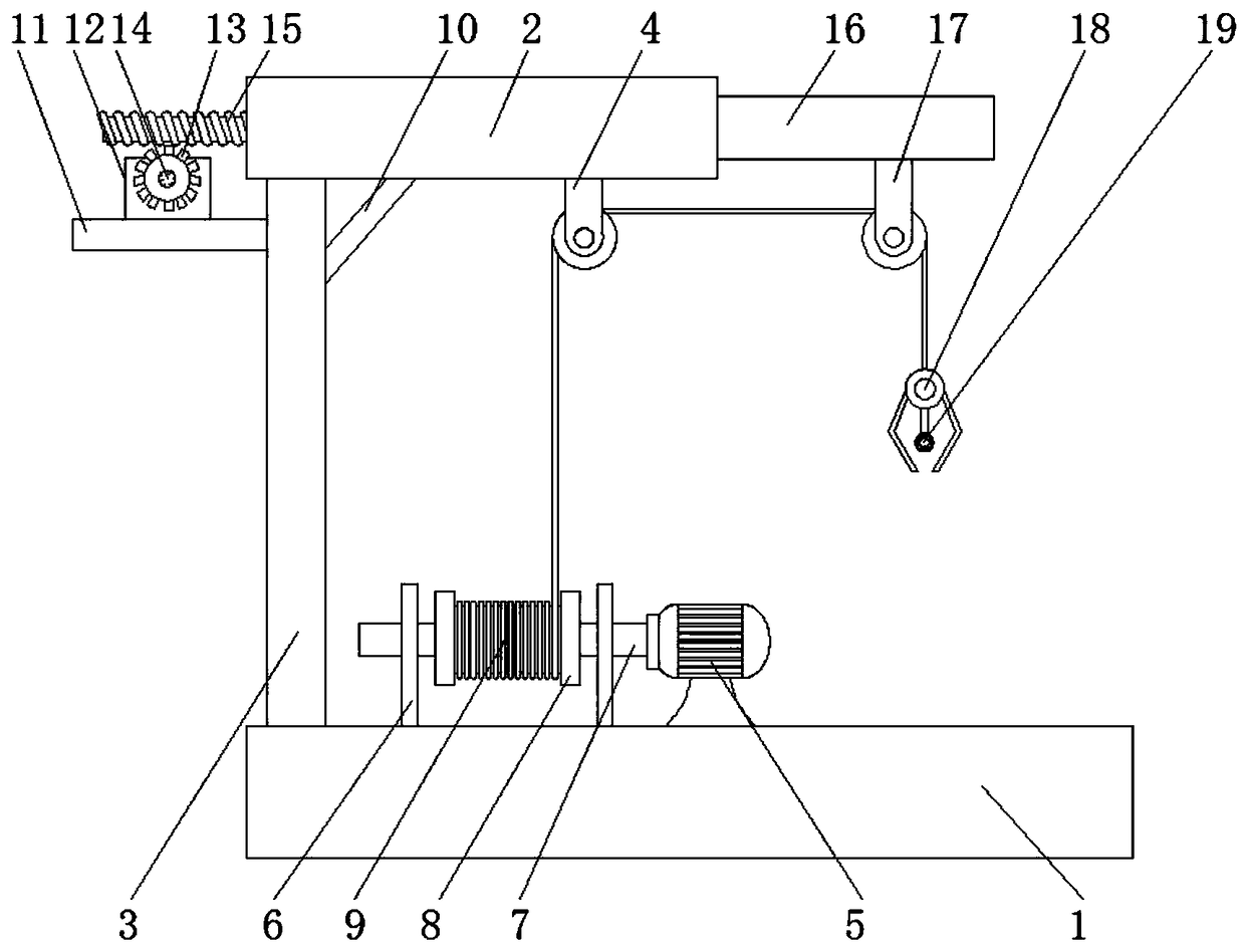
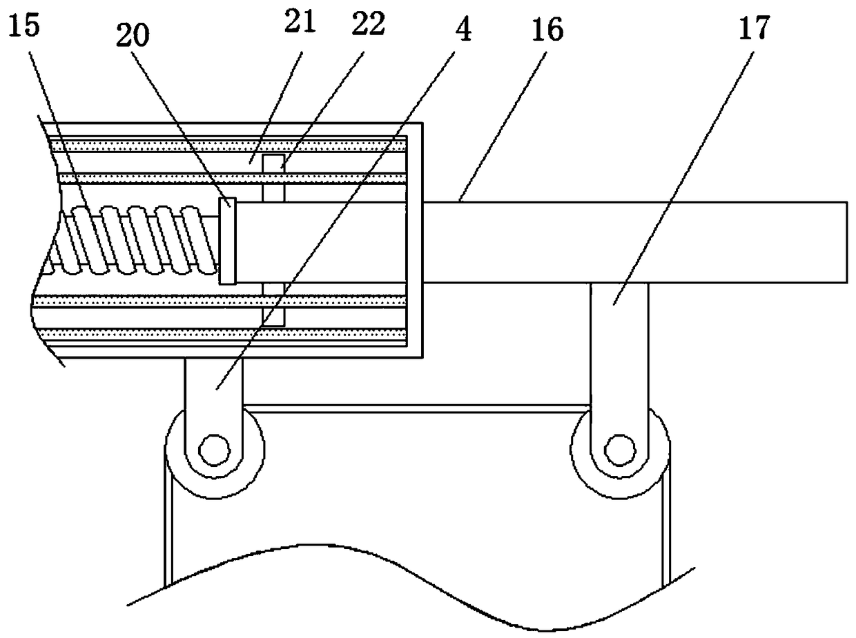
[0019] refer to Figure 1-2 , a ship hoisting device, comprising a device base 1 and a beam 2, a steel column 3 is fixedly installed on the upper surface of the device base 1 close to the beam 2, and the device base 1 is connected to the lower surface side of the beam 2 through the steel column 3, and the steel A bottom plate 11 is provided on the top of one side of the column 3, and an angle steel 10 is fixedly installed between the steel column 3 and the beam 2 away from the bottom plate 11, and the lower surface of the beam 2 close to the angle steel 10 is provided with a first fixed pulley 4, and the base of the device The upper surface of 1 is provided with a co...


PUM


Abstract

The invention discloses a ship hoisting device. The ship hoisting device comprises a device base and a cross beam, wherein a steel column is fixedly arranged on the upper surface close to the cross beam of the device base; a bottom plate is arranged on the top of the outer wall of one side of the steel column; angle steel is fixedly arranged at a position far away from the bottom plate between thesteel column and the cross beam; the lower surface close to the angle steel of the cross beam is provided with a first fixed pulley; the upper surface of the device base is provided with a copper core motor and a limiting frame; a rotation rod is movably arranged at one end passing through the limiting frame of the copper core motor; the outer surface of the rotation rod is sleeved with a coilingsleeve; the upper surface of the bottom plate is provided with a positive-negative rotation motor; a threaded rod is arranged at a position at which the cross beam passes through one side wall. The hoisting device is more convenient for pulling out and withdrawing a traction line, and the moving range of the coiling sleeve is fixed. Meanwhile, ship hoisting operation under different distances canbe realized. The ship hoisting device is novel in structure, and has very high practicability.

Description

technical field [0001] The invention relates to the technical field of ship engineering, in particular to a ship hoisting device. Background technique [0002] After the hull structure is pre-assembled to form sections or general sections, it needs to be transported to the berth with a hoisting device and then assembled and welded to form the entire hull, that is, the general assembly of the hull, also known as large closing. On the basis of assembly and welding, general section assembly and welding, outfitting and painting, the overall assembly and welding of the ship and the process of outfitting and painting are completed on the berth, which is directly related to ensuring the quality of ship construction and shortening the construction period of ships. , when the traditional hoisting device is in use, when the ship is hoisted with the traction rope, the range of motion of the coil sleeve is not limited, which brings inconvenience to the use of the device. At the same tim...

Claims


Application Information

Patent Timeline
Patent Type & Authority Applications(China)
IPC IPC(8): B66C23/04B66C23/62B66D3/06
CPCB66C23/04B66C23/62B66D3/06
Inventor 王正阳
Owner 芜湖籁余新能源科技有限公司
Why Eureka
Try Eureka