Concrete-filled steel tubular column-concrete-filled steel tubular beam joint connection structure

A technology of concrete-filled steel pipe columns and concrete-filled steel pipes, which is applied to truss structures, columns, joists, etc., can solve problems such as difficulty in cross-installation of bolts, heavy welding workload, and high technical requirements for workers, and achieve efficient and convenient on-site construction and welding work Large quantity and good economical effect

Pending Publication Date: 2018-12-11
SHENYANG POLYTECHNIC UNIV
View PDF10 Cites 1 Cited by
  • Summary
  • Abstract
  • Description
  • Claims
  • Application Information

AI Technical Summary

Problems solved by technology

[0005] Although the traditional full-bolt connection reduces the workload of on-site welding, it has the disadvantage that it is difficult to install the bolts on the same horizontal plane. At the same time, during the concrete pouring process, it may be difficult for the coarse aggregate to pass through the crossed bolts, resulting in incomplete pouring. produce
[0006] The traditional external reinforcement ring connection, internal reinforcement ring connection and externally extending internal partition connection require a large amount of welding work. Although part of the welding can be done in the factory, the connection between the beam and the column wall still needs to be welded on site. Especially when welding at an elevation angle, there is a problem of difficult welding angles, which requires high technical requirements for workers
For the connection joints of internal reinforcing ring and externally extending internal diaphragm, there are still difficulties in welding inside the steel pipe

Method used


Image

  • Concrete-filled steel tubular column-concrete-filled steel tubular beam joint connection structure
  • Concrete-filled steel tubular column-concrete-filled steel tubular beam joint connection structure
  • Concrete-filled steel tubular column-concrete-filled steel tubular beam joint connection structure

Examples


Embodiment Construction

[0036] Below in conjunction with accompanying drawing, the present invention will be further described:

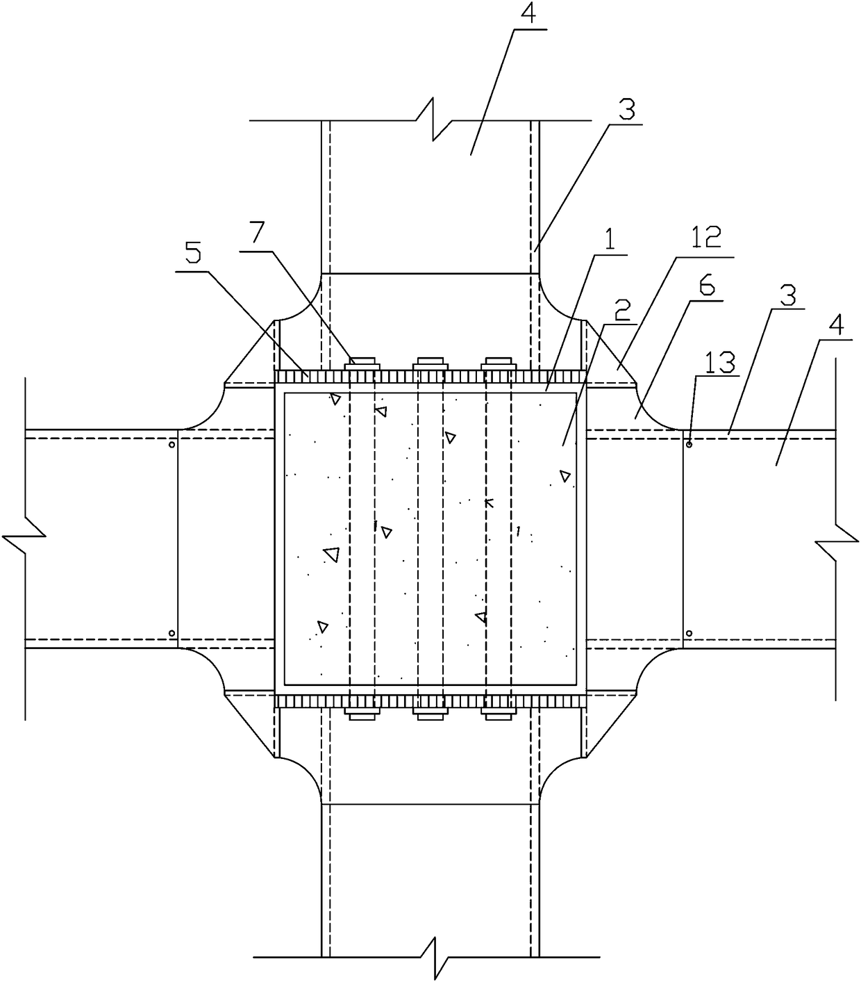
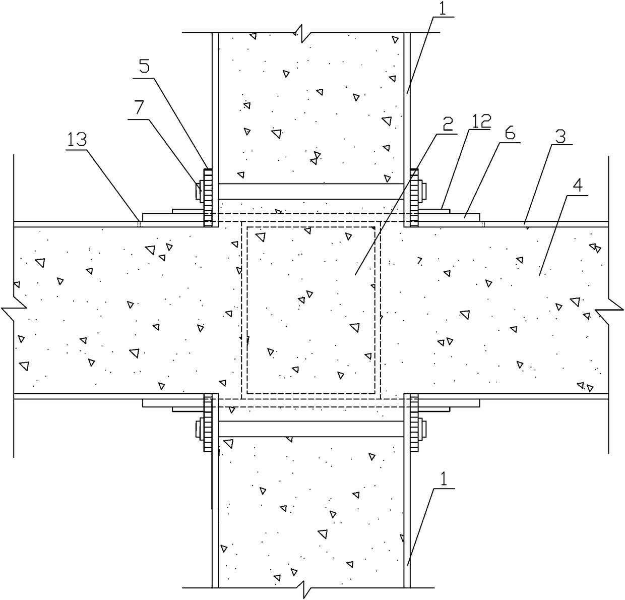
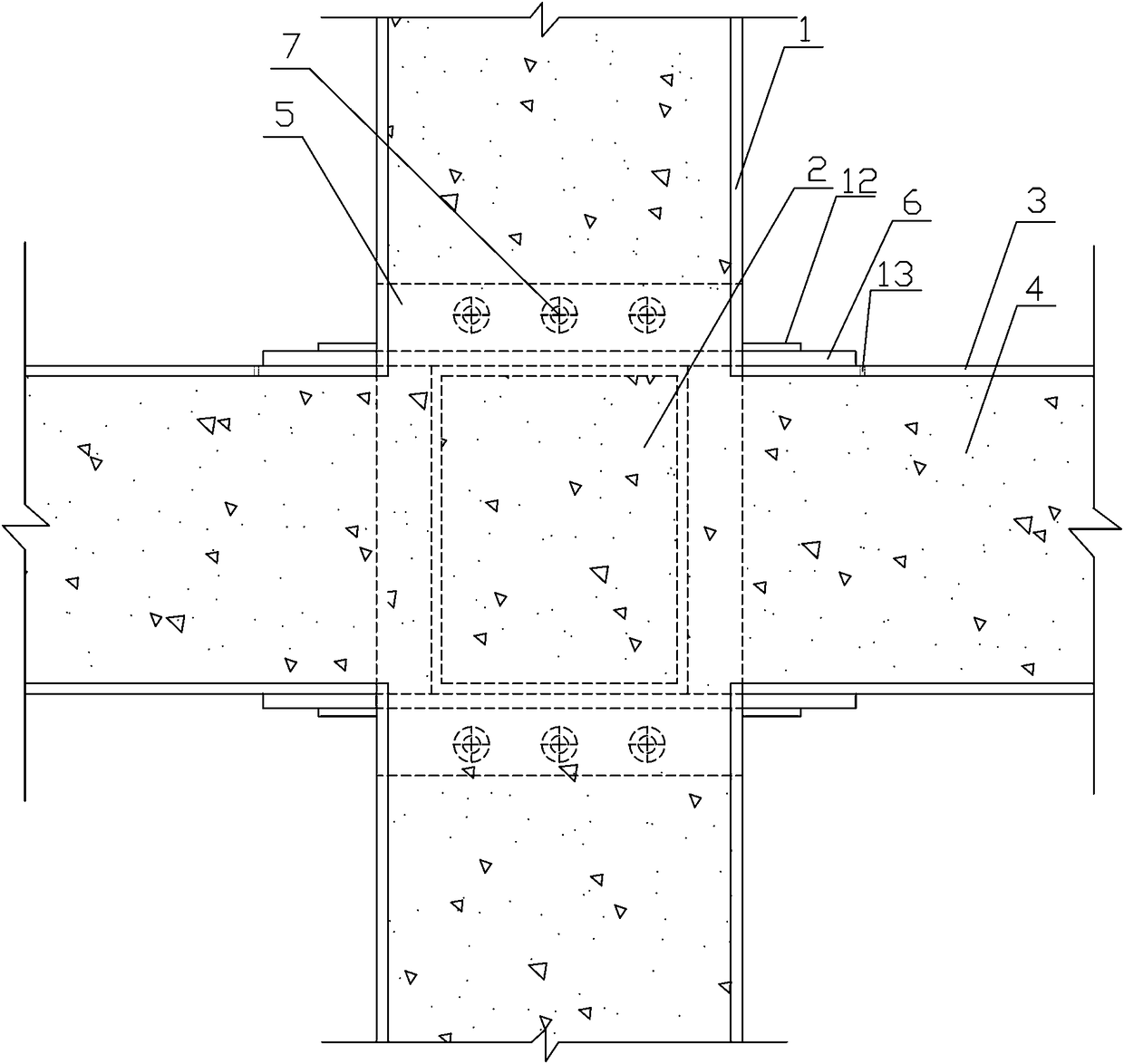
[0037] Such as figure 1 , figure 2 , image 3 , Figure 4 , Figure 5 , Figure 6 , Figure 7 , Figure 8 , Figure 9 , Figure 10 and Figure 11As shown, a concrete-filled steel tube column-concrete-filled steel beam joint connection structure includes a concrete-filled steel tube column 8, a concrete-filled steel tube beam 11, a perforated end plate 5, a T-shaped reinforcement plate 6, bolts 7, a triangular piece 12, and a concrete-filled steel tube column 8 It is composed of steel pipe 1 outside the column and concrete 2 inside the column. The concrete-filled steel pipe beam 11 is composed of steel pipe 3 outside the beam and concrete 4 inside the beam. The steel pipe 1 outside the column of the concrete-filled steel pipe column 8 has a rectangular opening around it. The size of the rectangular opening is the same as that of the concrete-filled steel pipe beam...


PUM


Abstract

The invention, which belongs to the field of building structural engineering, relates to a concrete-filled steel tubular column-concrete-filled steel tubular beam joint connection structure. Rectangular openings are formed around an outer-column steel tube of a concrete-filled steel tubular column; one end of each of four concrete-filled steel tubular beams including a front concrete-filled steeltubular beam, a rear concrete-filled steel tubular beam, a left concrete-filled steel tubular beam, and a right concrete-filled steel tubular beam is against one rectangular opening correspondingly; and T-shaped reinforced plates are welded to the upper walls and the lower walls of outer-beam steel tubes of the left concrete-filled steel tubular beam and the right concrete-filled steel tubular beam and are also welded to the outer-column steel tube of the concrete-filled steel tubular column body. The concrete-filled steel tubular column is connected with perforated end plates at the front wall and rear wall of the outer-column steel tube by bolts respectively. T-shaped reinforced plates are welded to the upper walls and the lower walls of outer-beam steel tubes of the front concrete-filled steel tubular beam and the rear concrete-filled steel tubular beam and are also welded to perforated end plates simultaneously. Triangular pieces are welded to all adjacent T-shaped reinforced plates and thus the T-shaped reinforced plates of all adjacent outer-beam steel tubes are connected into one. The force can be transmitted clearly; the on-site welding work load is low; the manufacturing and construction become convenient; the engineering quality is easy to control; and the work hours are saved.

Description

technical field [0001] The invention belongs to the field of building structure engineering and relates to a steel tube concrete structure, in particular to a node connection structure design of a steel tube concrete column-steel tube concrete beam. Background technique [0002] Due to its many advantages, the steel tube concrete structure has been popularized and applied to high-rise and super high-rise buildings, highway arch bridges and other fields, and its development is very rapid. It is an indisputable fact that the comprehensive economic benefits obtained by the construction of the steel pipe concrete structure. At present, the most common application in existing buildings is to connect steel pipe concrete columns with steel beams or reinforced concrete beams to form a frame structure. However, it is still in its infancy to apply the combination of CFST columns and CFST beams into an integral frame structure. [0003] The connection node between the beam and the co...

Claims


Application Information

Patent Timeline
Patent Type & Authority Applications(China)
IPC IPC(8): E04B1/21E04C3/34E04C3/20
CPCE04B1/21E04C3/20E04C3/34
Inventor 王颖毕灵云王家鑫徐金花
Owner SHENYANG POLYTECHNIC UNIV
Why Eureka
Try Eureka