Method using aluminum formwork to pour floor roof

A technology of aluminum mold and roof plate, which is applied in the field preparation of formwork/formwork/work frame, building components, construction, etc., can solve the problems of low transfer efficiency, reduce labor intensity, avoid repeated handling, and improve The effect of construction efficiency

Active Publication Date: 2018-12-11
CONSTR COMPANY OF CHINA RAILWAY NO 8 ENGNEERING GRP +1
View PDF6 Cites 0 Cited by
  • Summary
  • Abstract
  • Description
  • Claims
  • Application Information

AI Technical Summary

Problems solved by technology

[0003] During the construction process of the existing aluminum formwork, the aluminum formwork and other small-sized construction equipment will be reused sequentially between the upper and lower floors under construction. The aluminum formwork disassembled from the lower floor needs to be transported to the upper floor. In the existing technology, it is often necessary to use a crane or a hanging tower to transfer the aluminum formwork upwards from the outside of the building, and the workers need to carry it repeatedly, resulting in the problem of low transfer efficiency

Method used


Image

  • Method using aluminum formwork to pour floor roof
  • Method using aluminum formwork to pour floor roof
  • Method using aluminum formwork to pour floor roof

Examples


Embodiment 1

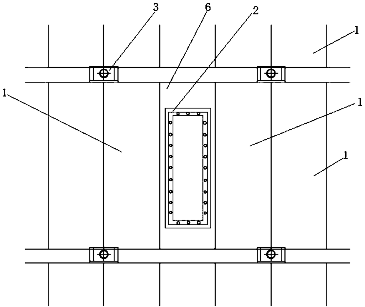
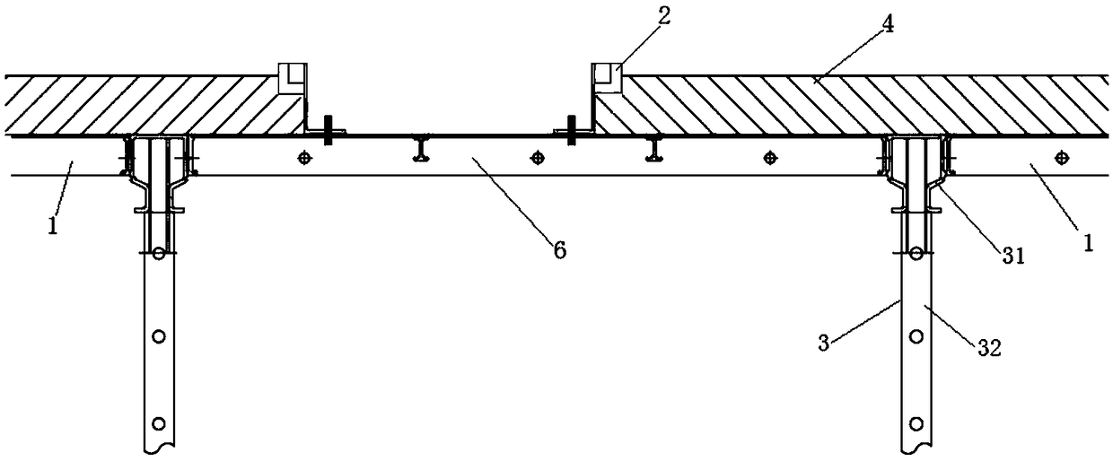
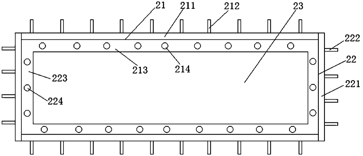
[0036] Such as Figure 1-2 As shown, the aluminum formwork 2 used to make the material transfer hole, when the top floor 4 is poured on the floor foundation that has completed the bottom floor pouring, includes a continuously tiled top formwork 1, and the lower part of the top formwork 1 is supported at even intervals. The supporting device 3, the supporting device includes a supporting top seat 31 on the top and a push rod 32 under the supporting top seat; the top formwork 1 is also provided with an aluminum mold assembly 2, when the top floor 4 is poured , can form material transfer holes on the top floor, used for transferring aluminum formwork and other building materials and small operating tools from the lower floor to the upper floor. Specifically, the aluminum mold assembly 2 includes side plates 21 and end plates 22 , which are connected to each other to form a rectangular cavity 23 . After the top floor 4 is poured, the aluminum formwork 2 and the top formwork 1 can...

Embodiment 2

[0043] Such as Figure 8-10As shown, the difference between this embodiment and embodiment 1 lies in the difference of the aluminum formwork assembly. The aluminum formwork assembly 7 used to make the material transfer hole in this embodiment is welded by aluminum formwork, and the whole is an inverted hollow Quadrangle truss structure; the aluminum template assembly 7 includes a quadrangular pedestal subassembly 71, and a quadrangular prism upper assembly 72 that expands in equal proportions on the upper edge of the quadrangular pedestal subassembly, the quadrangular pedestal upper assembly The lower edge of the body 72 is connected with the upper edge of the lower assembly 71 of the quadrangular platform through a horizontal step portion 73 .

[0044] The outer surface around the aluminum mold assembly 7 is evenly spaced with a number of vertical ribs 74, the bottom of the vertical ribs 74 is located in the middle of the lower assembly 71 of the square platform, and the top ...

Embodiment 3

[0049] Such as Figure 10 , 11 As shown, the supporting device 3 includes a support top seat 31 and a support rod 32 formed under the support top seat 31. The support top seat 31 can use some existing top seats with supporting functions, and in this embodiment in, such as Figure 11-12 As shown, the supporting top seat 31 includes a top seat bottom plate 311, and two parallel and spaced top seat splints 312 arranged longitudinally along the top seat bottom plate 311, the distance between the two top seat splints 312 is not less than two top templates 4 The total thickness of the formwork side plates at the joints of the ends, the support top seat 31 is inserted into the ejector rod 32 through the top seat support column 313 at the bottom, and when the ends of the two top formworks 4 are aligned, the support top seat 31 can be The formwork side panels of the top formwork 4 are sandwiched between two top seat splints 312 to form an effective support.

[0050] The lower part o...


PUM


Abstract

The invention discloses a method using aluminum formwork to pour a floor roof. The method has the advantages that by mounting a matched aluminum combined body for manufacturing a conveying hole, the conveying hole can be formed after top floor pouring to allow small-sized building equipment such as aluminum formwork to be conveniently conveyed from a lower layer to an adjacent upper layer, the useof large machinery is avoided, repeated carrying by workers is avoided, worker labor intensity is lowered, and construction efficiency is increased effectively.

Description

technical field [0001] The invention belongs to the technical field of building construction, and in particular relates to a method for pouring a floor roof by using aluminum molds. Background technique [0002] Aluminum formwork is a building formwork made of aluminum alloy. The aluminum formwork is extruded by special equipment. It is composed of three parts: aluminum panel, bracket and connector. The overall formwork with complex dimensions of different sizes and the system formwork for assembly and industrial construction have solved the defects of traditional formwork in the past and greatly improved construction efficiency. The aluminum formwork system is suitable for building construction with a high degree of standardization. It has the advantages of short construction period, many times of repeated use, convenient construction, good stability, high bearing capacity, wide application range, less seams, high precision, good concrete surface effect after form removal,...

Claims


Application Information

Patent Timeline
IPC IPC(8): E04G15/06E04G11/48
CPCE04G11/48E04G11/483E04G15/063
Inventor 杨华超邱军罗鹏杨波张超洋姜淑清冉华寇利红王昭蒋健
Owner CONSTR COMPANY OF CHINA RAILWAY NO 8 ENGNEERING GRP
Why Eureka
Try Eureka