Continuous surface anti-corrosion device for copper alloy production

An anti-corrosion device, copper alloy technology, applied in the direction of metal material coating process, etc., can solve the problems of increasing the waste of anti-corrosion liquid, wasting time and effort, reducing the speed and uniformity of anti-corrosion treatment, and achieving faster speed and uniformity, and accelerated flow response , cost-saving effect

Inactive Publication Date: 2021-02-09
冯振福
View PDF0 Cites 0 Cited by
  • Summary
  • Abstract
  • Description
  • Claims
  • Application Information

AI Technical Summary

Problems solved by technology

[0003] However, in the current technology, the continuous surface anticorrosion device for copper alloy production generally divides soaking and drying into two processes, resulting in: 1. It is time-consuming and laborious to transport copper alloy repeatedly; 2. There is no setting for the recovery of anticorrosion liquid vapor, which increases 3. Without the setting of mobile spraying, it cannot accelerate the flow reaction of anticorrosion solution on the surface of copper alloy, which reduces the speed and uniformity of anticorrosion treatment

Method used


Image

  • Continuous surface anti-corrosion device for copper alloy production
  • Continuous surface anti-corrosion device for copper alloy production
  • Continuous surface anti-corrosion device for copper alloy production

Examples


Embodiment 1

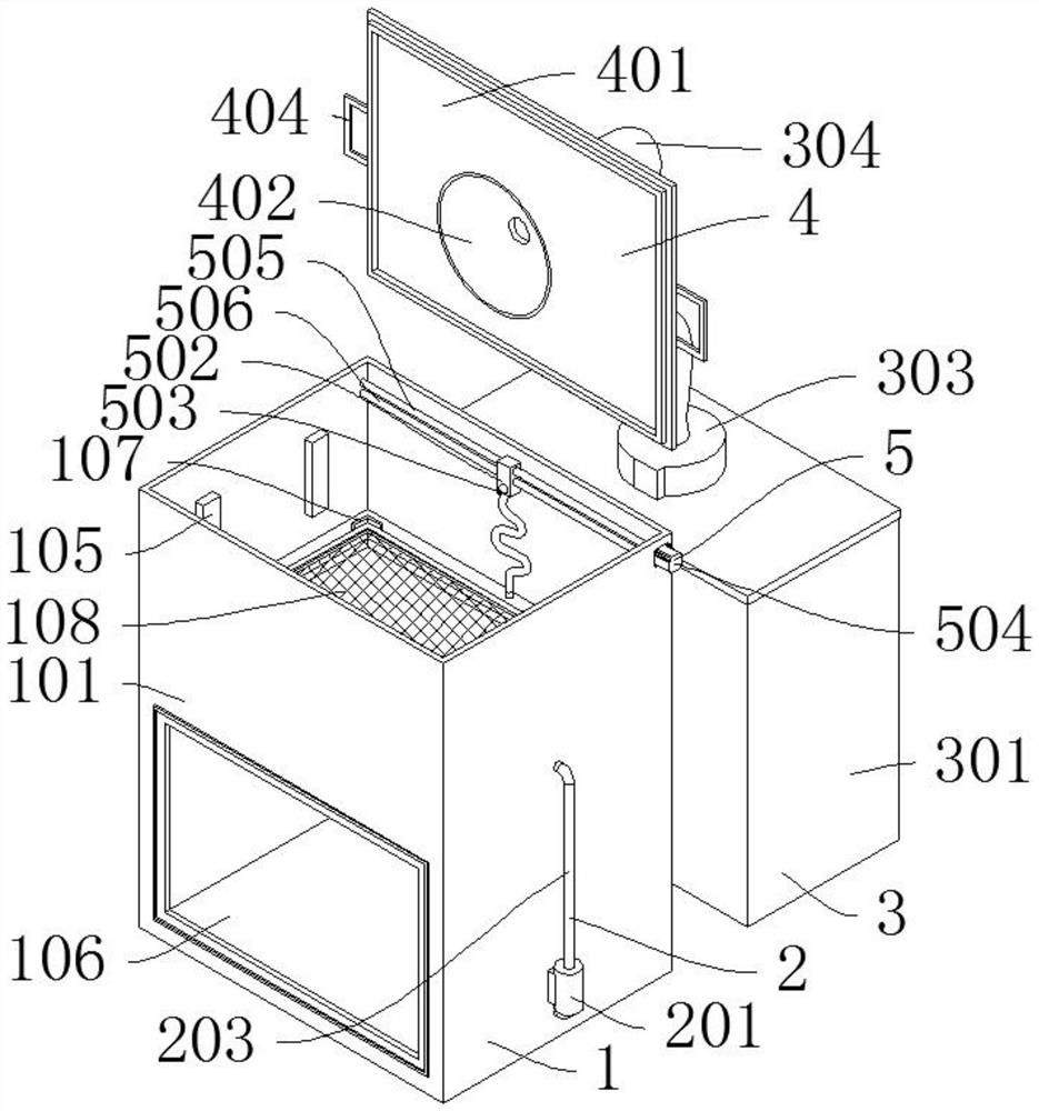
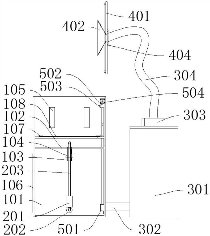
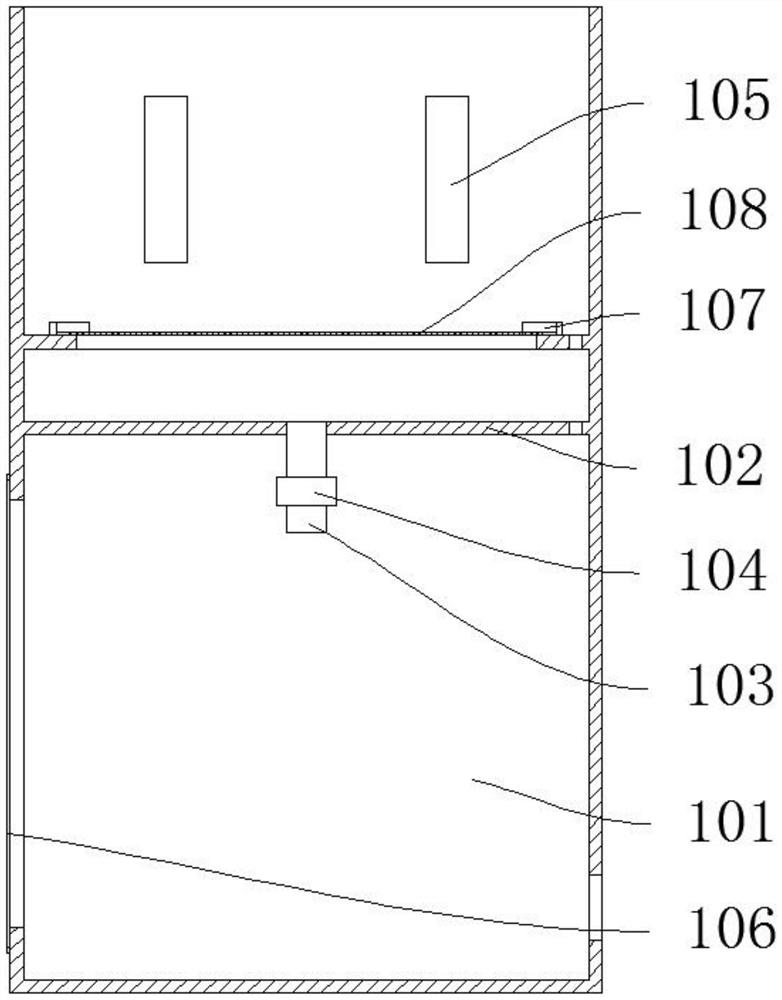
[0044] Such as Figure 1-Figure 7As shown, a continuous surface anti-corrosion device for copper alloy production includes a main box device 1 for soaking copper alloy. An infusion device 2 for delivering anti-corrosion liquid is installed on one side of the main box device 1, and a useful The sub-tank device 3 for steam liquefaction, the top of the sub-tank device 3 is equipped with a cover device 4 for closing the main tank device 1, and the inner wall of the main tank device 1 is equipped with a spraying device 5 for spraying anti-corrosion liquid; the main tank device 1 includes the main tank device 1 Casing 101, a transparent plate 106 is arranged on the front of the main casing 101, a partition 102 is arranged in the middle of the main casing 101, a drain pipe 103 is arranged in the middle of the partition 102, and a drain valve 104 is installed on the drain pipe 103, and the partition A limit support plate 107 is arranged above the plate 102, a support net 108 is instal...

Embodiment 2

[0047] Such as Figure 8 As shown, the difference between Embodiment 2 and Embodiment 1 is that the spraying device 5 includes a second water pump 501, a second support block 507 is arranged above the second water pump 501, and a spray head 503 is installed in front of the second support block 507. A linear motor 509 is installed behind the block 507, and a guide rail 508 is arranged behind the linear motor 509. The linear motor 509 drives the first support block 502 and the nozzle 503 to move along the guide rail 508. The second water pump 501 extracts the anti-corrosion liquid and sprays it through the nozzle 503 to accelerate copper Alloy surface anticorrosion fluid flow reaction; the second water pump 501 is connected to the nozzle 503 by pipelines, the linear motor 509 is connected to the second support block 507 by bolts, the guide rail 508 is connected to the main box 101 by bolts, and the pipeline connection ensures the circulation of the anticorrosion fluid. The bolt ...


PUM


Abstract

The invention discloses a continuous surface anti-corrosion device for copper alloy production. A main box device used for soaking a copper alloy is included, a liquid conveying device used for conveying anti-corrosion liquid is arranged on one side of the main box device, and an auxiliary box device used for steam liquefaction is arranged behind the main box device. An upper cover device used forsealing the main box device is installed at the top of the auxiliary box device, and a spraying device used for spraying the anti-corrosion liquid is installed on the inner wall of the main box device. Through integrated arrangement, repeated carrying of the copper alloy is avoided, and time and labor are saved; through the arrangement of anti-corrosion liquid steam recovery, the waste of the anti-corrosion liquid is reduced, and the cost is saved; and through the arrangement of movable spraying, the flowing reaction of the anti-corrosion liquid on the surface of the copper alloy is accelerated, and the anti-corrosion treatment speed and uniformity are improved.

Description

technical field [0001] The invention relates to the technical field of copper alloy production, in particular to a continuous surface anticorrosion device for copper alloy production. Background technique [0002] The reason for the rusting of copper is that after the copper parts have been machined, the oxide film on the copper surface has been destroyed, or other remaining metal elements have oxidized with oxygen, water vapor, and carbon dioxide in the air to form a green patina. Copper alloy anti-corrosion treatment is to use the strong oxidizing substances in the copper anti-tarnish agent to promote the active metal ions on the metal surface to change into a passive state, which is not easy to be oxidized. [0003] However, in the current technology, the continuous surface anticorrosion device for copper alloy production generally divides soaking and drying into two processes, resulting in: 1. It is time-consuming and laborious to transport copper alloy repeatedly; 2. Th...

Claims


Application Information

Patent Timeline
Patent Type & Authority Applications(China)
IPC IPC(8): C23C22/76
CPCC23C22/76
Inventor 冯振福杨勇飞
Owner 冯振福
Why Eureka
Try Eureka