
Multi-stage yielding contracting type steel frame based on constant-resistance sliding hole shearing losses and connection method thereof

A sliding hole and steel frame technology, which is applied in earthwork drilling, wellbore lining, tunnel lining, etc., can solve the problems that the construction effect of retractable steel frame is difficult to guarantee, the timing of transition cannot be effectively controlled, and the sliding resistance is unstable. Achieve the effect of not increasing the construction process, easy to promote, and simple construction

Active Publication Date: 2018-12-11
KUNMING SURVEY DESIGN & RES INST OF CREEC
View PDF6 Cites 5 Cited by
  • Summary
  • Abstract
  • Description
  • Claims
  • Application Information

AI Technical Summary

Problems solved by technology

The steel arch frame of the traditional telescopic steel frame uses steel pipes and U-shaped steel that need to be customized. The snap ring of the shrinkable joint provides sliding resistance through bolt fastening. The initial sliding resistance is related to the torque of the snap ring. After starting to slide, the snap ring may become loose, and the sliding resistance is unstable. The resistance provided by the steel frame is difficult to quantify, and the timing cannot be effectively controlled.
[0005] Therefore, according to the large deformation characteristics of the surrounding rock, the early deformation of the surrounding rock can be reasonably controlled, the pressure of the surrounding rock can be properly released, and the load acting on the structure can be reduced. Difficult to guarantee

Method used


Image

  • Multi-stage yielding contracting type steel frame based on constant-resistance sliding hole shearing losses and connection method thereof
  • Multi-stage yielding contracting type steel frame based on constant-resistance sliding hole shearing losses and connection method thereof
  • Multi-stage yielding contracting type steel frame based on constant-resistance sliding hole shearing losses and connection method thereof

Examples


Embodiment Construction

[0034] The preferred embodiments of the present invention will be described in detail below in conjunction with the accompanying drawings, so that the advantages and features of the present invention can be more easily understood by those skilled in the art, so as to define the protection scope of the present invention more clearly.

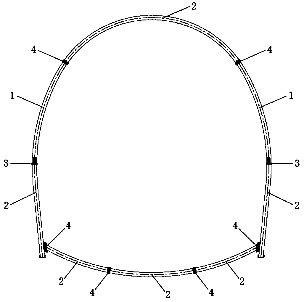
[0035] Such as figure 1 Shown is a schematic arrangement of a multi-stage yielding compressible steel frame joint based on constant resistance sliding hole shear loss, including a shrinkable steel frame unit 1, a common steel frame unit 2, a shrinkable joint 3, and a common joint 4. Generally, two shrinkable joints are arranged for each steel frame, symmetrically arranged according to the center line of the tunnel section. Common joint 4 is the traditional steel frame joint that adopts steel plate, angle steel and bolt connection.

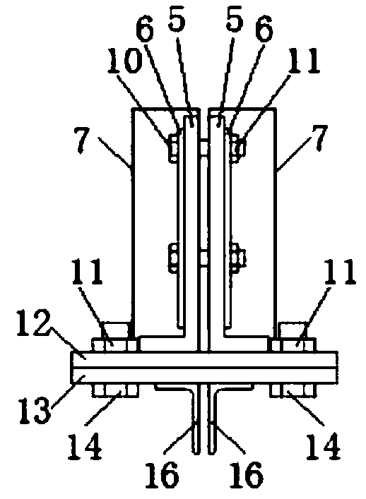
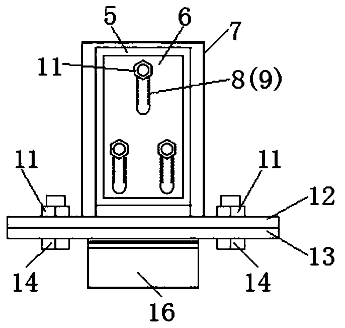
[0036] Such as Figure 2-5 As shown, the shrinkable joint 3 is composed of an L-shaped support 5, a constant resi...


PUM


Abstract

The invention discloses a multi-stage yielding contracting type steel frame based on constant-resistance sliding hole shearing losses and a connection method thereof. The multi-stage yielding contracting type steel frame comprises a contracting type steel frame unit, an ordinary steel frame unit, a contracting type joint and a common joint. A sliding end of the contracting type steel frame unit isconnected with the ordinary steel frame unit through the contracting type joint; the contracting type steel frame unit can be contracted in the contracting type joint; and the ordinary steel frame unit employs a common joint for connection. According to the invention, the contracting type joint is connected with the steel frame unit firmly and the steel frame has the certain bending-resistant andshearing-resistant performances; a sliding assembly employs a protection cover for protection, so that the influence on the joint by concrete spraying is avoided greatly; with full utilization of themechanical property of the steel product, the profile steel, steel plate, bolt and the like are ordinary materials at a construction site, so that processing becomes convenient and material are simple and easy to use; all assemblies are dismounted conveniently and no construction procedure is increased; welding and slot hole opening are carried out on the contracting type steel frame joint; splicing is carried out in a tunnel; the construction is done simply and conveniently; and the multi-stage yielding contracting type steel frame and the connection method thereof are easy to popularize.

Description

technical field [0001] The invention belongs to the technical field of tunnel engineering support, and in particular relates to a multi-stage yielding compressible steel frame based on constant resistance sliding hole shear loss and a connection method. Background technique [0002] With the continuous increase of the construction scale of tunnel projects such as transportation, energy, and water conservancy in my country, large deformation problems are often encountered in tunnel projects passing through soft rock sections with high geostress. Its unique "expansion", "extrusion" and "looseness" make the tunnel diameter shrink, the surrounding rock stress is large, the deformation speed is fast, the convergence and stability time is long, and it even cannot converge, and the deformation is large. During the protection, the supporting structure is subjected to great surrounding rock pressure, which leads to damage. During the construction of the large deformation tunnel, vari...

Claims


Application Information

Patent Timeline
IPC IPC(8): E21D11/22
CPCE21D11/22
Inventor 田鲁鲁杨进京郭永发殷洪波丁文云杜建军徐涛张海波陶伟明杨翔罗云飞罗胜利刘正初赵海燕李贵民
Owner KUNMING SURVEY DESIGN & RES INST OF CREEC
Learn More