
Power heat pipe inter-column air conditioning system

A technology of inter-column air conditioners and power heat pipes, applied in the field of power heat pipe type inter-column air-conditioning systems, can solve the problems of insufficient driving force and unsatisfactory height difference, etc., and achieve the effect of wide application range

Pending Publication Date: 2018-12-11
BEIJING NYF SCI & TECH DEV CO LTD
View PDF0 Cites 3 Cited by
  • Summary
  • Abstract
  • Description
  • Claims
  • Application Information

AI Technical Summary

Problems solved by technology

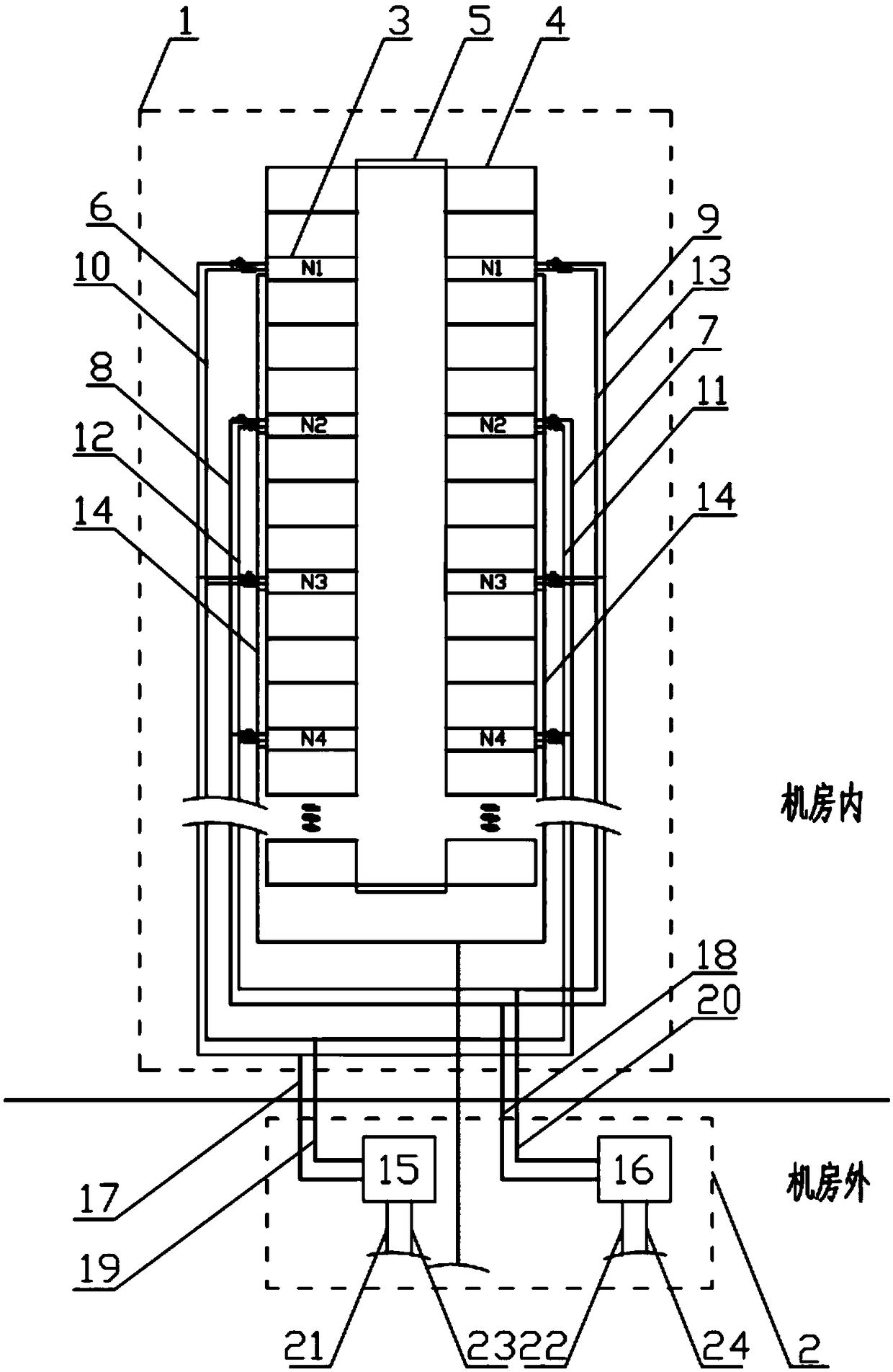
[0008] Aiming at the shortcomings and deficiencies of the prior art, the present invention aims to provide a power heat pipe type inter-column air-conditioning system, which adopts the dual backup mode of the system. Ensure that one of the two heat pipe inter-row air conditioners arranged oppositely can operate normally, so as to ensure the heat dissipation requirements of adjacent cabinets; the use of refrigerant pumps to drive the flow of refrigerant has a wide range of applications, especially suitable for solving the problem of traditional gravity heat pipes due to the condensing end. The height difference of the evaporation end cannot meet the problem of insufficient driving force caused by the too long connecting pipeline of the system; the adoption of the monitoring system enables all the data of the system to be uploaded to the upper computer of the system, which is conducive to the timely monitoring and adjustment of various functional indicators

Method used


Image

  • Power heat pipe inter-column air conditioning system
  • Power heat pipe inter-column air conditioning system
  • Power heat pipe inter-column air conditioning system

Examples


Embodiment Construction

[0036]In order to make the object, technical solution and advantages of the present invention clearer, the present invention will be further described in detail below with reference to the accompanying drawings and examples.

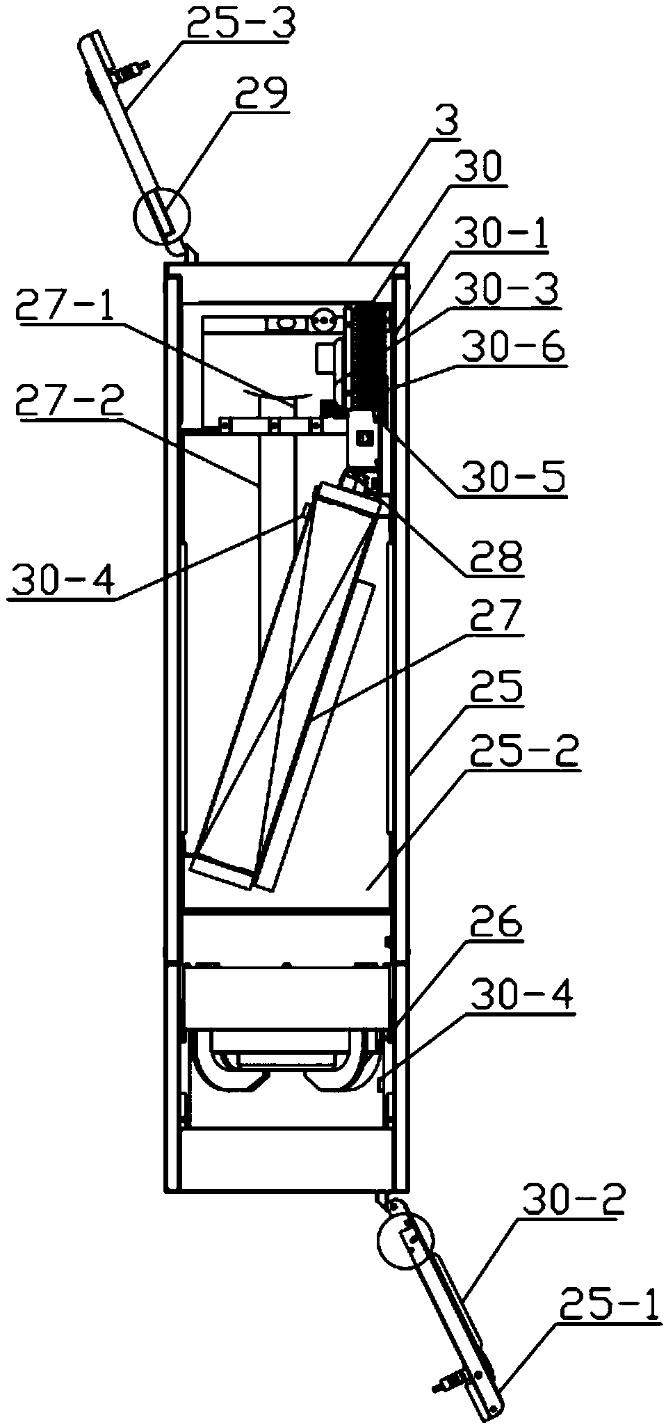
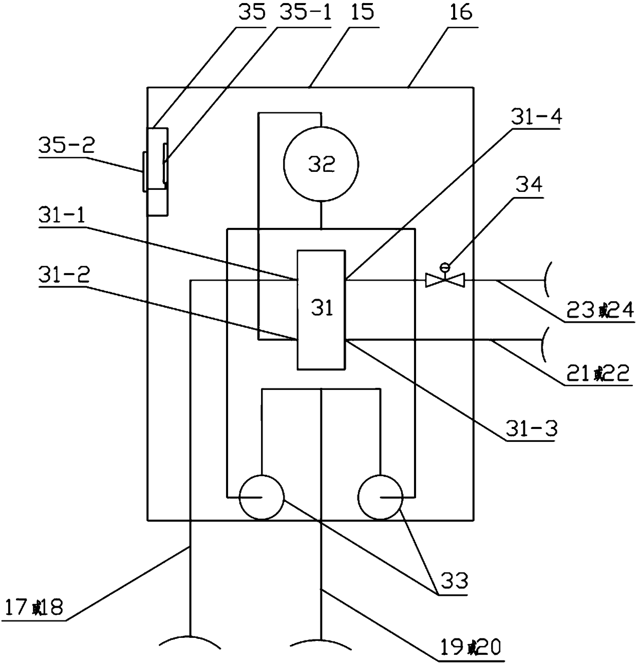
[0037] figure 1 It is a schematic diagram of the power heat pipe type inter-row air-conditioning system of the present invention. As shown in the figure, the power heat pipe type inter-row air-conditioning system of the present invention includes a closed channel module 1 installed in the machine room, and an intermediate heat exchange unit 2 installed outside the machine room, wherein the closed channel module 1 includes two oppositely arranged Several heat pipe inter-column air conditioners 3, several cabinets 4, 1 set of closed channel components 5, air collecting pipe I6, air collecting pipe II7, air collecting pipe III8, air collecting pipe IV9, liquid pipe I10, liquid pipe II11, liquid pipe III12 , liquid distribution pipe IV13, water collection p...


PUM


Abstract

The invention provides a power heat pipe inter-column air conditioning system. Odd-numbered positions of first columns and even-numbered positions of second columns of heat pipe inter-column air conditioners are connected to a water-fluorine heat exchange host I; and even-numbered positions of the first columns and odd-numbered positions of the second columns are connected to a water-fluorine heatexchange host II. By adopting the system double backup mode, when one set of heat exchange loop fails, the other set of heat exchange loop operates normally, one of the two opposite heat pipe inter-column air conditioners can operate normally, and the heat dissipation requirements of adjacent cabinets can be ensured; a refrigerant pump is used for driving a refrigerant to flow, the application range is wide, the refrigerant pump is especially suitable for solving the problem that a conventional gravity heat pipe cannot reach the height difference between a condensation end and an evaporationend or driving force is insufficient due to a too long system connection pipe; and by adopting a monitoring system, all system data can be uploaded to a system upper computer, and various functional indicators can be conveniently monitored and adjusted in time.

Description

technical field [0001] The invention relates to the field of heat exhaustion in a machine room, in particular to a dynamic heat pipe type inter-row air conditioning system. Background technique [0002] The integration density of cabinet servers in the computer room is getting higher and higher, and the heat generated by the server is getting larger and larger. In order to ensure that the servers in the high heat dissipation density computer room work at the most suitable ambient temperature, the current heat dissipation method of the high heat dissipation density computer room is also constantly changing. . [0003] At present, there are mainly the following methods for heat dissipation in high heat dissipation density computer rooms: [0004] One is precise air supply from the precision air conditioner. In this way, air ducts are used in the machine room to direct the cold air from the precision air conditioner to the server cabinet. The main advantage is that the cold ai...

Claims


Application Information

Patent Timeline
IPC IPC(8): F24F1/00F24F13/30F24F11/89
CPCF24F1/0007F24F11/89F24F13/30
Inventor 刘志辉冯剑超周健健许荣兴庞晓风杨贤云孙兴义
Owner BEIJING NYF SCI & TECH DEV CO LTD
Learn More