Heuristic rule system based crankshaft wearing detection method for industrial robot

A technology of industrial robots and detection methods, which is applied in the testing of machines/structural components, machine gears/transmission mechanisms, and testing of mechanical components. To ensure the accuracy of detection and other issues

Active Publication Date: 2018-12-11
HANGZHOU DIANZI UNIV
View PDF7 Cites 7 Cited by
  • Summary
  • Abstract
  • Description
  • Claims
  • Application Information

AI Technical Summary

Problems solved by technology

It has been found through practice that the selection of the pulse size has a great influence on the degree of wear detected, which makes the measurement results full of uncertainties and it is difficult to g

Method used


Image

  • Heuristic rule system based crankshaft wearing detection method for industrial robot
  • Heuristic rule system based crankshaft wearing detection method for industrial robot
  • Heuristic rule system based crankshaft wearing detection method for industrial robot

Examples


Embodiment Construction

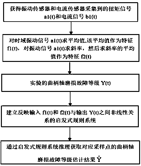
[0042] A kind of heuristic rule system-based industrial robot crankshaft wear detection method, the method comprises the following steps:

[0043] (1) Use the torque signal a1(t) and current signal b1(t) collected by the vibration sensor and current sensor installed on the servo motor of the industrial robot, where the torque unit is mm, the current signal unit is A, a1(t) ∈[-4,2], b1(t)∈[-4,4], the torque signal and the current signal are sampled at the same time every 1 second, a total of T times, 1000≤T<∞, then the sampling time t =1,2,...,T.

[0044] (2) When the current signal is stable, calculate the average value of the time-domain vibration signal a1(t) obtained in step (1), and use the average value as the feature f1(t), calculate the slope of the vibration signal a1(t), and then Find the average of the slopes as the feature f2(t).

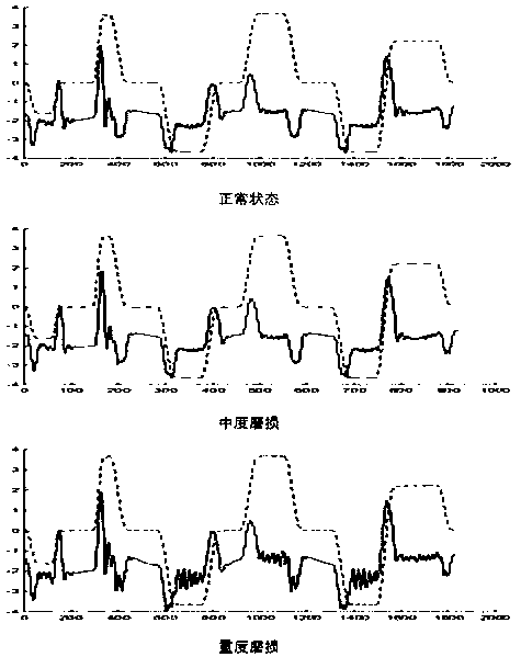
[0045] (3) The output is determined as the crankshaft wear failure level, and the crankshaft is qualitatively divided into three diffe...


PUM


Abstract

The invention relates to a heuristic rule system based crankshaft wearing detection method for an industrial robot. A heuristic rule system is used for modeling, and a nonlinear mapping relation between variables f1 and f2 (input) of the torque mean value and torque derivative mean value of a crankshaft of the industrial robot and a wearing degree variable Y (output) of the same is described. Vialimited historical data, the initial model of the heuristic rule system is optimized, and influence of subjective factors on the model is reduced. The heuristic rule system method can be used to calculate parameters of the model in a simpler and rapider way, so that the wearing degree of the crankshaft of the industrial robot can be estimated accurately and rapidly by interference of the heuristicrule system under the condition that the torque mean value and torque deviation mean value features are given. The model estimation precision and calculation efficiency are improved, the efficiency is higher, and more advantages are provided.

Description

technical field [0001] The invention relates to an industrial robot crank shaft wear detection method based on a heuristic rule system, belonging to the field of industrial production safety maintenance. Background technique [0002] With the improvement of the degree of automation and the beat of the production line, industrial robots operating at high speeds and high loads have frequent failures, among which the incidence of failures caused by the wear of the robot crank shaft is the highest. Since the crank of the robot crank shaft is also used as the input and output of the second-stage cycloidal wheel transmission, after it is worn out, it has a great impact on the positioning accuracy of the robot, and it is accompanied by abnormal noise and vibration, which greatly reduces the service life of the robot. There may even be serious safety accidents. [0003] Some scholars have studied that in the wear detection of motor cylindrical roller bearings, contour detection is ...

Claims


Application Information

Patent Timeline
IPC IPC(8): G01M13/02G01R19/00
CPCG01M13/028G01R19/0092
Inventor 徐晓滨赵状状翁旭李建宁侯平智黄大荣王晓兵
Owner HANGZHOU DIANZI UNIV
Why Eureka
Try Eureka