Combined relay coil and its design method for bipolar wireless charging system

A relay coil, combined technology, used in charging stations, electric vehicle charging technology, electric vehicles, etc., can solve the problem of inability to meet the requirements of charging distance and efficiency, the failure of the relay function of the annular relay coil, and the lack of IPT systems. Following the structure and other problems, it can achieve the effect of expanding the effective charging area, shortening the simulation calculation time, and reducing the number of samples.

Active Publication Date: 2021-12-07
SHANGHAI UNIVERSITY OF ELECTRIC POWER
View PDF5 Cites 0 Cited by
  • Summary
  • Abstract
  • Description
  • Claims
  • Application Information

AI Technical Summary

Problems solved by technology

[0004] 1. The current wireless charging system based on the principle of magnetic coupling has a limited charging distance, which cannot meet the requirements of many working environments for charging distance and efficiency
[0005] 2. At present, the research on the relay coil of wireless power transmission mainly focuses on the MRC system, and there is no research on the relay structure of the IPT system
[0006] 3. Most of the high-power applications of wireless power transmission use bipolar coils, which leads to the failure of the relay function of traditional circular relay coils.
[0007] 4. The general relay coil structure can only increase the transmission distance, and does not improve the anti-offset performance of the system
[0008] 5. When the general flat coil is used as a relay coil, in order to ensure the utilization of the magnetic flux on both sides, the magnetic core cannot be installed, and the relay effect is not significant
[0009] In view of the above reasons, the research results of traditional relay coils are difficult to be applied to applications requiring high power and high anti-offset capability, such as electric vehicle wireless charging.

Method used


Image

  • Combined relay coil and its design method for bipolar wireless charging system
  • Combined relay coil and its design method for bipolar wireless charging system
  • Combined relay coil and its design method for bipolar wireless charging system

Examples


Embodiment Construction

[0039] The present invention will be described in detail below in conjunction with the accompanying drawings and specific embodiments. This embodiment is carried out on the premise of the technical solution of the present invention, and detailed implementation and specific operation process are given, but the protection scope of the present invention is not limited to the following embodiments.

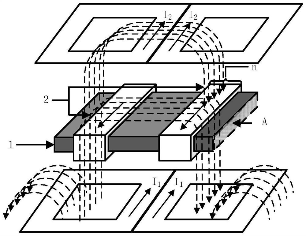
[0040] like figure 1 As shown, the present invention provides a combined relay coil for a bipolar wireless charging system, which is arranged between the transmitting coil and the receiving coil, and includes a magnetic core 1 and a plurality of separate windings wound on the magnetic core 1 2. Multiple separate windings 2 are arranged at intervals, and the area A of the side surface of the magnetic core 1 is the effective area.

[0041] In some embodiments, the magnetic core 1 can be a ferrite core.

[0042] In some embodiments, the magnetic core 1 can be an H-shaped magnetic core,...


PUM


Abstract

The invention relates to a combined relay coil for a bipolar wireless charging system and a design method thereof. The combined relay coil is arranged between a transmitting coil and a receiving coil, and comprises a magnetic core and a plurality of magnetic cores wound around the magnetic Separate windings on the core, a plurality of the separate windings are arranged at intervals. Compared with the prior art, the present invention can not only improve the efficiency of the system, but also enhance the anti-offset capability of the system and expand the effective charging area of ​​the system.

Description

technical field [0001] The invention relates to the technical field of wireless power transmission, in particular to a combined relay coil for a bipolar wireless charging system and a design method thereof. Background technique [0002] The use of the relay coil can greatly increase the transmission distance of the wireless power transmission system. Due to the limitation of effective charging area and relative transmission height of planar toroidal coils, new bipolar coils, such as double D pad (DDP), are widely used in wireless charging of electric vehicles. Planar toroidal relay coils cannot be applied in bipolar coil systems due to the limited fit between the coils. [0003] The relay coil of the current wireless power transfer system still has the following deficiencies: [0004] 1. The current wireless charging system based on the principle of magnetic coupling has a limited charging distance, which cannot meet the requirements of many working environments for chargi...

Claims


Application Information

Patent Timeline
Patent Type & Authority Patents(China)
IPC IPC(8): H02J50/10H02J50/50H02J50/70B60L53/12
CPCH02J50/10H02J50/50H02J50/70Y02T10/70Y02T10/7072Y02T90/14
Inventor 夏能弘朱益民
Owner SHANGHAI UNIVERSITY OF ELECTRIC POWER
Why Eureka
Try Eureka