Motor driving method and device and air conditioner
A motor drive and current technology, applied in the direction of controlling electromechanical transmission, controlling electromechanical brakes, controlling generators, etc., can solve problems such as component damage and adverse effects on component reliability
- Summary
- Abstract
- Description
- Claims
- Application Information
AI Technical Summary
Problems solved by technology
Method used
Image
Examples
no. 1 example
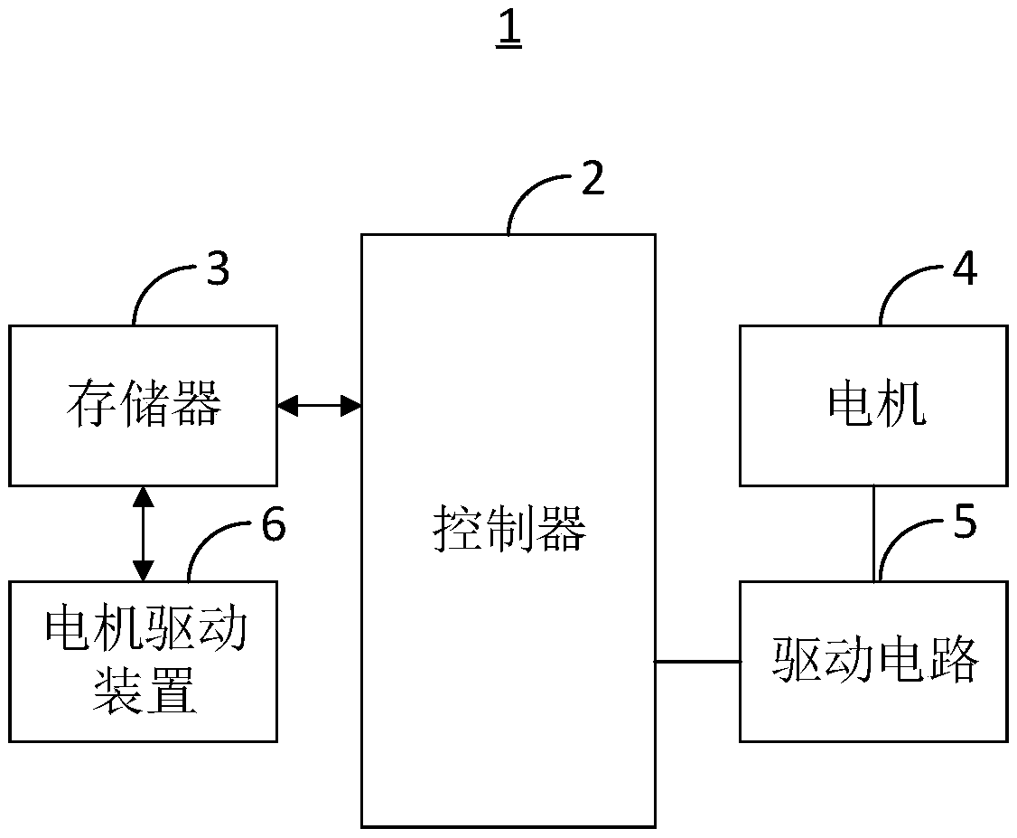
[0056] The embodiment of the present invention provides an air conditioner 1, which is used to adjust the indoor temperature while avoiding the influence of peak current on the stability of components. see figure 1 , is a functional block diagram of the air conditioner 1 provided by the embodiment of the present invention. The air conditioner 1 includes: a controller 2 , a memory 3 , a motor 4 , a driving circuit 5 and a motor driving device 6 . Wherein, the controller 2 is electrically connected to the memory 3 and the drive circuit 5 , and the drive circuit 5 is electrically connected to the motor 4 . The motor driving device 6 includes at least one device that can be stored in the memory 3 in the form of software or firmware.
[0057] Wherein, the memory 3 can be used to store software programs and units, such as the program instructions / units corresponding to the motor drive device 6 and the method in the embodiment of the present invention, and the controller 2 runs the...
no. 2 example
[0061] The embodiment of the present invention provides a motor driving method, which is applied to the air conditioner 1 described in the first embodiment, and is used to realize the function of driving the motor 4 while avoiding the impact of the peak current generated when the input voltage is low in the traditional technology. impact on component stability. see Figure 4 , is a flowchart of a motor driving method provided by an embodiment of the present invention. The motor drive method includes:
[0062] Step S401: Obtain input voltage, bus voltage and phase current input to a motor 4 .
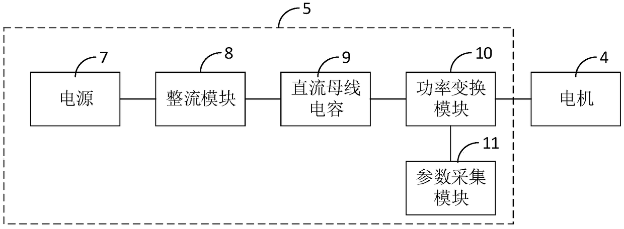
[0063] It can be understood that the input voltage, the bus voltage and the phase current input to a motor 4 can be collected by the parameter collection module 11 .
[0064] In addition, in this embodiment, the phase currents input to the motor 4 include the u-phase current i u and v-phase current i v .
[0065] Step S402: Calculate the q-axis torque current given value according ...
no. 3 example
[0121] see Figure 7 , Figure 7 A functional block diagram of a motor drive device 6 provided by a preferred embodiment of the present invention. It should be noted that the basic principles and technical effects of the motor drive device 6 provided in this embodiment are the same as those of the above-mentioned embodiment. corresponding content. The motor drive device 6 includes: a parameter acquisition unit 12 , a calculation unit 13 , a voltage given amount determination unit 14 and a pulse width modulation signal generation unit 15 .
[0122] Wherein, the parameter obtaining unit 12 is used to obtain the input voltage, the bus voltage and the phase current input to a motor 4 .
[0123] It can be understood that, in a preferred embodiment, the parameter acquisition unit 12 can be used to execute step S401.
[0124] The calculation unit 13 is used to calculate the q-axis torque current given value according to the bus voltage, the phase current, and the preset rotationa...
PUM
 Abstract
Description
Claims
Application Information
 - R&D
- Intellectual Property
- Life Sciences
- Materials
- Tech Scout
- Unparalleled Data Quality
- Higher Quality Content
- 60% Fewer Hallucinations
Browse by: Latest US Patents, China's latest patents, Technical Efficacy Thesaurus, Application Domain, Technology Topic, Popular Technical Reports.
© 2025 PatSnap. All rights reserved.Legal|Privacy policy|Modern Slavery Act Transparency Statement|Sitemap|About US| Contact US: help@patsnap.com


