
Digital assisted locking circuit

A technology of locking circuits and circuits, applied in the direction of electrical components, automatic power control, etc., can solve the problems of prolonging the working time of modules, affecting the response time of the transceiver system, and large system power consumption, avoiding environmental changes, avoiding process deviations, The effect of fast response speed

Active Publication Date: 2018-12-11
XIDIAN UNIV
View PDF5 Cites 3 Cited by
  • Summary
  • Abstract
  • Description
  • Claims
  • Application Information

AI Technical Summary

Problems solved by technology

[0003] The locking time of the phase-locked loop is an important parameter to characterize the performance of the phase-locked loop. The length of the locking time directly affects the response time of the transceiver system. If the locking time is too long, the working time of the modules in the system will be extended, which will lead to excessive power consumption of the system.

Method used


Image

  • Digital assisted locking circuit
  • Digital assisted locking circuit
  • Digital assisted locking circuit

Examples


Embodiment Construction

[0024] In the following description, many technical details are proposed in order to enable readers to better understand the application. However, those skilled in the art can understand that the technical solutions claimed in this application can be realized even without these technical details and various changes and modifications based on the following implementation modes.

[0025] In order to make the object, technical solution and advantages of the present invention clearer, the present invention will be described in further detail below in conjunction with specific examples, but the implementation of the present invention is not limited thereto.

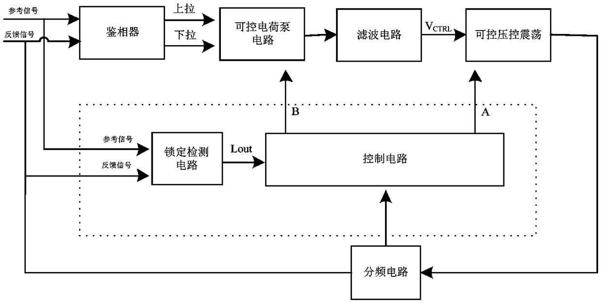
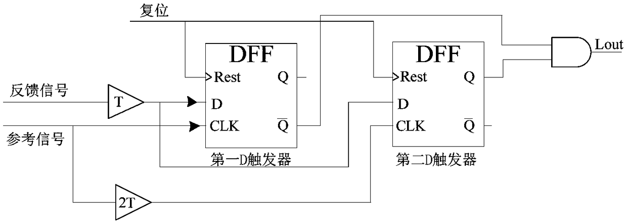
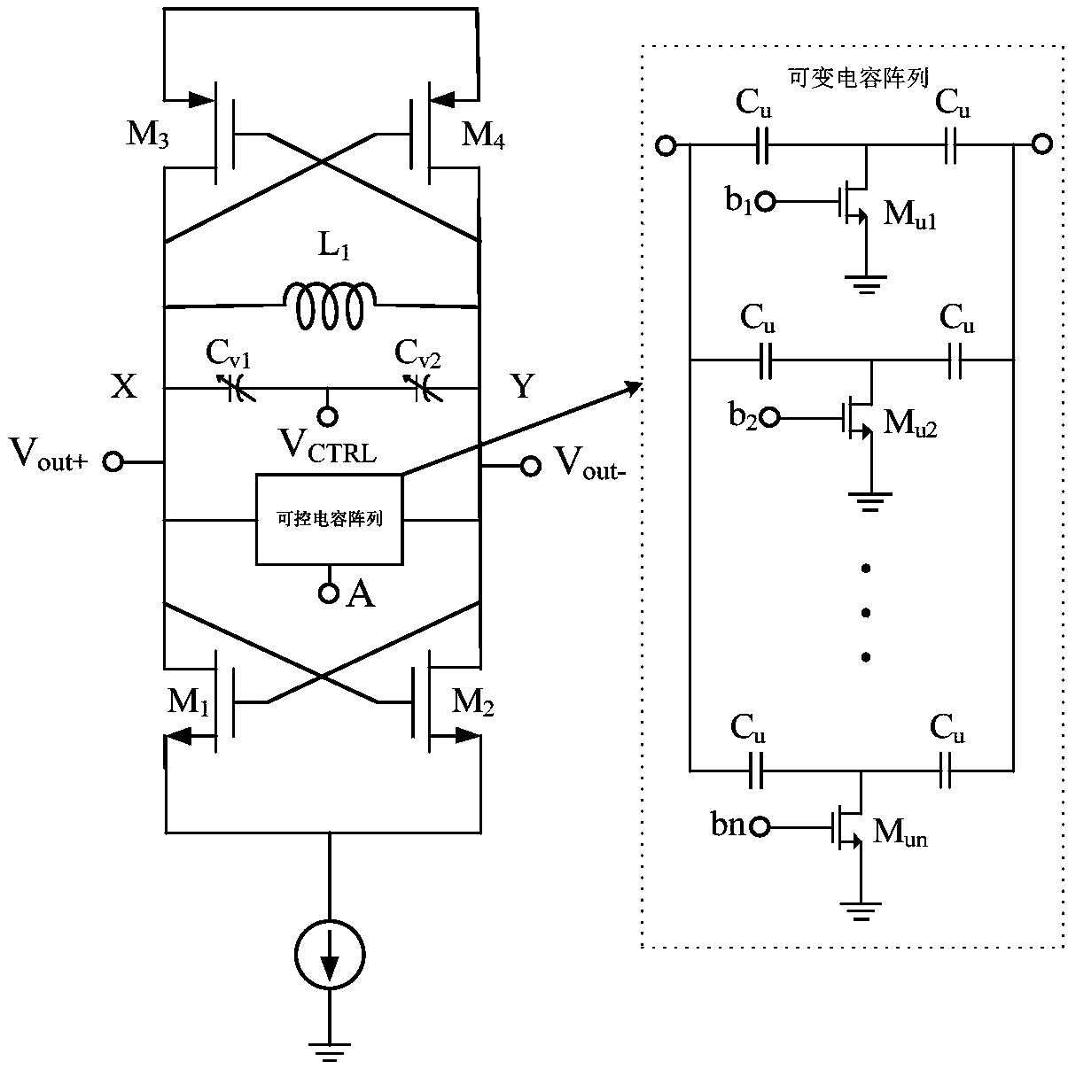
[0026] The implementation mode of the present application relates to a digital auxiliary locking circuit, figure 1 It is a digital auxiliary locking circuit diagram in the embodiment mode of the present invention. Such as figure 1 As shown, the digital assisted locking circuit consists of:

[0027] A lock detection circuit ...


PUM


Abstract

The invention relates to the field of radio frequency integrated circuit design, in particular to a digital auxiliary locking circuit, comprising a locking detection circuit and a control circuit, wherein the locking detection circuit is used for detecting a phase difference between a reference signal and a feedback signal from a frequency dividing circuit, and transmitting the phase difference signal to the control circuit. The control circuit is electrically connected to the frequency dividing circuit to receive a target frequency dividing signal transmitted by the frequency dividing circuit. The control circuit is electrically connected to the lock detection circuit to receive a phase difference signal sent by the lock detection circuit. This circuit reduces the number of times of the feedback-adjustment of phase locked loop (PLL), can effectively reduce the PLL loop lock time, to achieve the PLL fast lock function.

Description

technical field [0001] The invention relates to the field of radio frequency integrated circuit design, in particular to a digital auxiliary locking circuit of a phase-locked loop. Background technique [0002] PLLs can generate precise clock signals or frequency signals, so they are widely used in circuit systems such as clock generators, wireless communication systems, and clock / data recovery circuits. Frequency synthesizers based on phase-locked loops are widely used in radio frequency transceiver systems. These requirements have promoted the research and development of phase-locked loop circuits. [0003] The locking time of the phase-locked loop is an important parameter to characterize the performance of the phase-locked loop. The length of the locking time directly affects the response time of the transceiver system. If the locking time is too long, the working time of the modules in the system will be extended, which will lead to excessive power consumption of the s...

Claims


Application Information

Patent Timeline
Patent Type & Authority Applications(China)
IPC IPC(8): H03L7/099
CPCH03L7/099
Inventor 朱樟明周荣刘术彬黄胜刘帘曦
Owner XIDIAN UNIV
Learn More