
Novel multifunctional logging robot
A robotic and multi-functional technology, applied in the field of robotics, can solve problems such as low safety, low efficiency, and high risk, and achieve the effects of improving logging efficiency, improving work efficiency, and improving safety
- Summary
- Abstract
- Description
- Claims
- Application Information
AI Technical Summary
Problems solved by technology
Method used
Image

Examples
Embodiment Construction
[0034] Below in conjunction with accompanying drawing, technical scheme of the present invention is described in further detail:
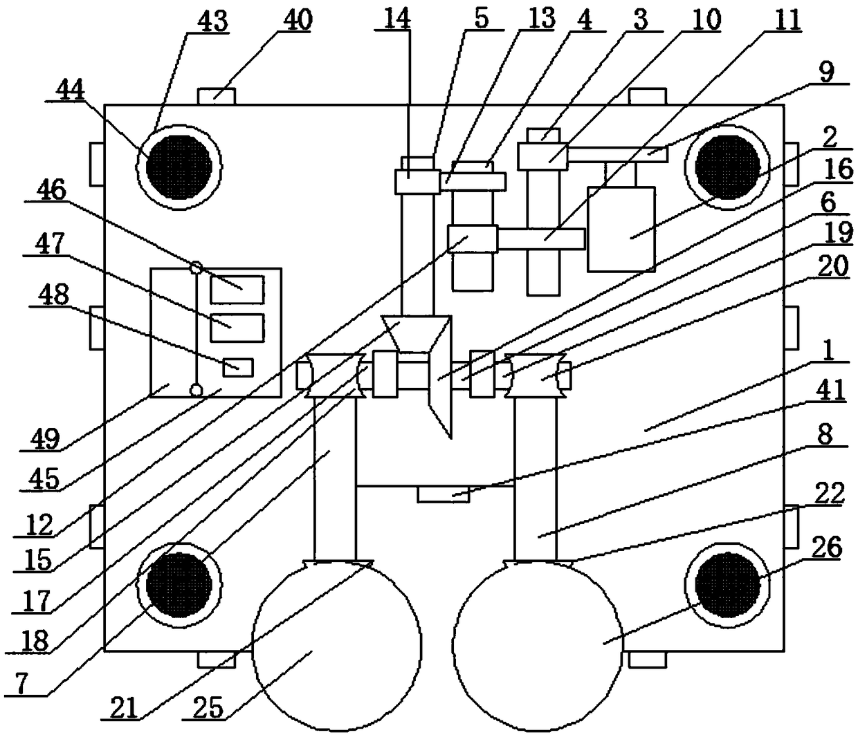
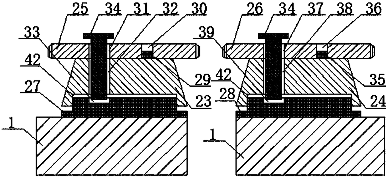
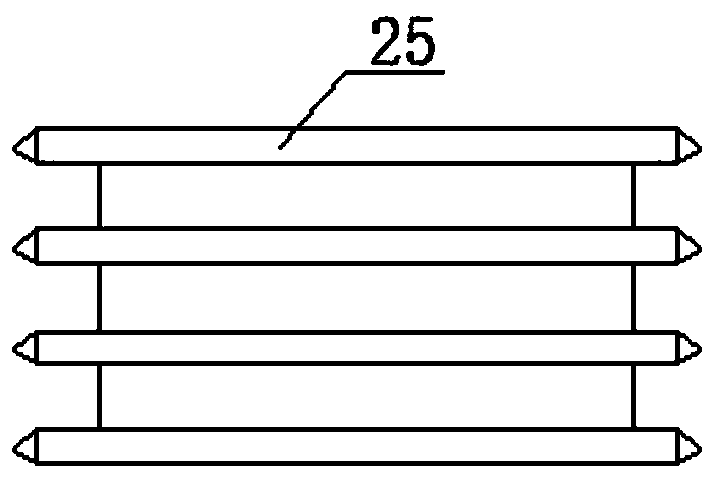
[0035] Such as Figure 1 to Figure 4As shown, a new type of multifunctional logging robot includes robot body 1, servo motor 2, axis I3, axis II4, axis III5, axis IV6, axis V7, axis VI8, large gear I9, small gear I10, large gear II11, Pinion II12, large gear III13, pinion III14, bevel gear I15, bevel gear II16, worm I17, turbine I18, worm II19, turbine II20, bevel gear III21, bevel gear IV22, bevel gear V23, bevel gear VI24, saw blade I25, saw blade II26, plane bearing I27 and plane bearing II28; the bottom end of the servo motor 2 is fixedly connected to the top end of the robot body 1, the shaft I3, shaft II4, shaft III5, shaft IV6, shaft V7, Shaft VI8 is rotationally connected with the top of the robot body 1 through bearings respectively; the large gear I9 is connected with the shaft of the servo motor 2 through a key, and the pinion I10 and...
PUM
 Abstract
Description
Claims
Application Information