Baby milk brewing machine

A technology of baby milk powder and milk making machine, which is applied in beverage preparation devices, household appliances, applications, etc. It can solve the problems of milk powder agglomeration, unsatisfactory users, water vapor easily entering the powder box, etc., and achieve the effect of switching

Active Publication Date: 2018-12-14
金华厚米健康科技有限公司
View PDF9 Cites 2 Cited by
  • Summary
  • Abstract
  • Description
  • Claims
  • Application Information

AI Technical Summary

Problems solved by technology

[0003] During the use of the above-mentioned patents, the high-temperature water cannot be quickly lowered to a lower temperature, and the water temperature can only be lowered by heat dissipation, which takes a long time to cool down and cannot meet the needs of users; and when milk is poured, water vapor easily enters the powder box to make the milk powder in the powder box agglomerate

Method used


Image

  • Baby milk brewing machine
  • Baby milk brewing machine
  • Baby milk brewing machine

Examples


Embodiment 1

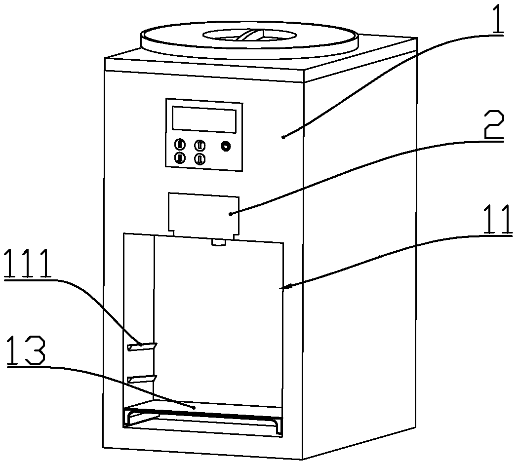
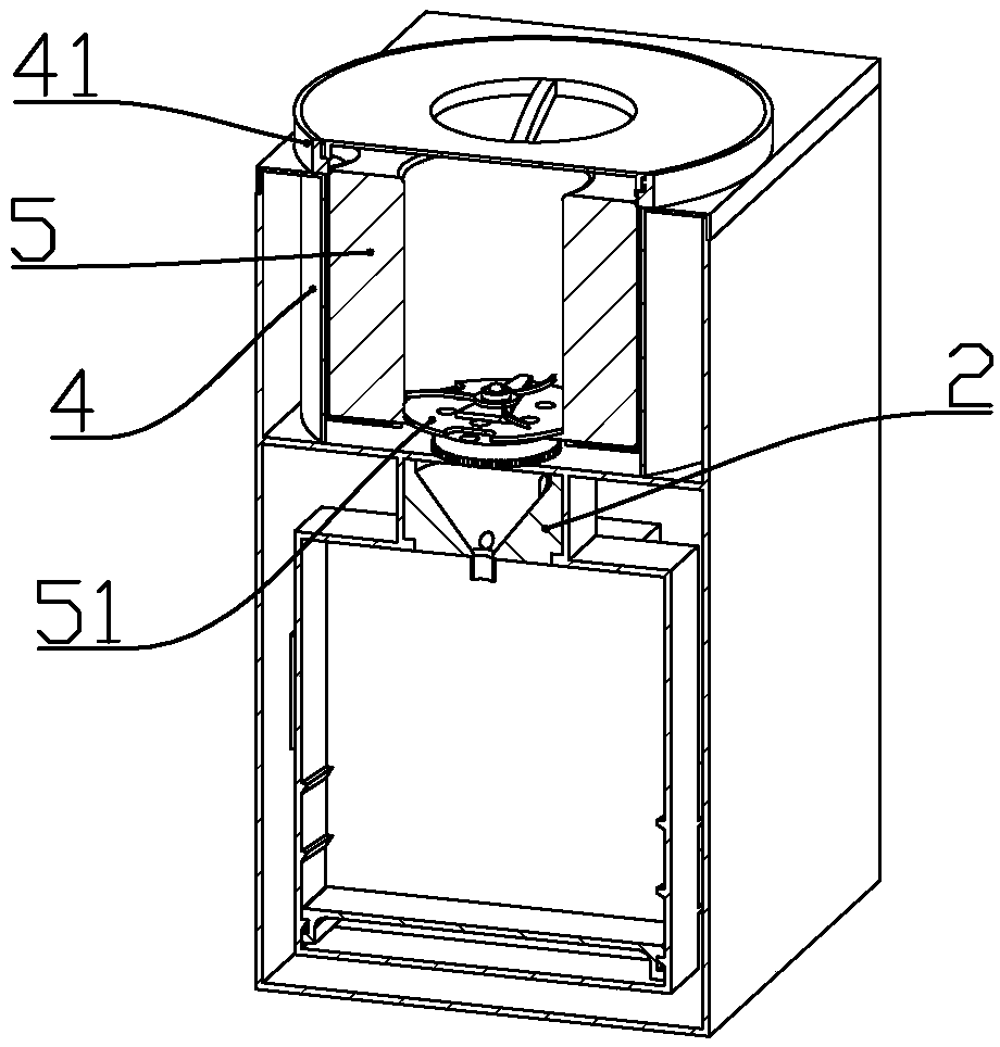
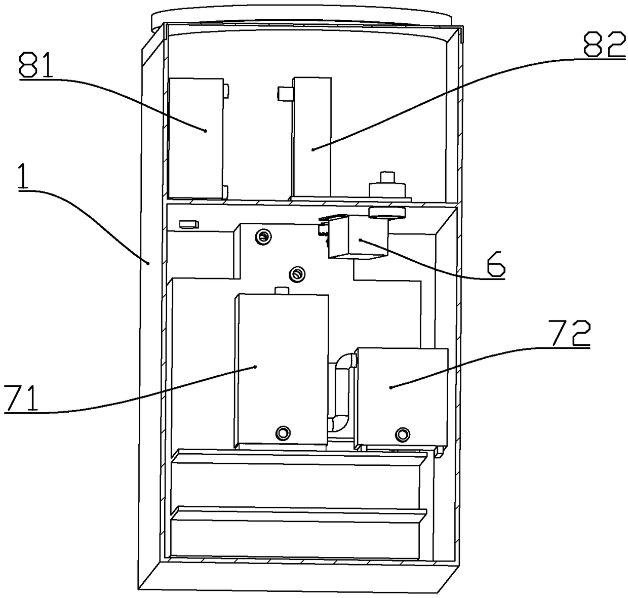
[0066] according to Figure 1 to Figure 25 As shown, a baby milk powder brewing machine described in this embodiment includes a housing 1; the housing includes a main body cavity 12, a feeding bottle placement cavity 11 located at the front end of the main cavity, and a cavity located at the upper end of the main cavity. Milk powder box assembly installation cavity 15.

[0067] A milk powder box assembly A for discharging milk powder is installed in the installation cavity of the milk powder box assembly; a water tank 31 is installed in the rear of the main body cavity.

[0068] The front end of the housing is located at the upper end of the feeding bottle placement cavity and a mixer installation cavity 14 is formed; a mixer 2 for mixing water and milk powder is installed in the mixer installation cavity; the top of the mixer installation cavity is formed to be useful In the cavity outlet 142 for milk powder to pass through.

[0069] The milk powder box assembly includes an...

Embodiment 2

[0151] according to Figure 26 As shown, this embodiment makes the following improvements on the basis of Embodiment 1: two sealing covers 401 are fixedly connected to the lower end of the discharge cover; the diameter of the sealing cover is larger than the diameter of the storage chamber; The sealing covers are respectively located at the upper ends of the non-working material storage chambers, and seal against the upper ends of the material storage chambers.

[0152] Because the two storage chambers that are not working are sealed against the sealing cover respectively, outside air cannot enter the storage chamber, so that the dryness in the storage chamber is kept, and the placement time of the milk powder is prolonged.

Embodiment 3

[0154] according to Figure 27 As shown, the difference between this embodiment and the preceding embodiments is that: the heating water tank is communicated with the mixer through a hose 93; the cold water tank is also communicated with the mixer through a hose.

[0155] Two rotating electromagnets 91 respectively used to control the water flow in the hose are installed in the installation cavity of the milk powder box assembly; Attach the eccentric wheel 911 to realize the cut-off.

[0156] An electromagnet mounting seat 92 is fixedly connected to the mounting cavity of the milk powder box assembly; the rotating electromagnet is fixedly connected to the electromagnet mounting seat; Pipe fixing seat 921; the hose is clamped in the hose fixing seat.

[0157] By controlling the rotating electromagnet to drive the eccentric wheel to work, the hose is cut off or circulated, and then the amount of hot water and cold water flowing out is controlled, so that the outflowing hot wat...


PUM


Abstract

The invention discloses a baby milk brewing machine. The machine comprises a housing. A milk powder box assembly used to discharge milk powders, a water tank, and a mixer used to mix water with the milk powders are arranged in the housing. The milk powder box assembly comprises an outer box body, an inner box body, and a material box. Three material storage cavities are formed on the material box.A rotating valve block is rotatably connected with the inner bottom of the material storage cavity. The upper end of the rotating valve block is connected with a catch and a powder stirring rotatingdisk. The side wall of the material storage cavity is provided with a catch vent groove. A material blowing channel is formed between a baffle and the catch. A main cavity is internally provided witha motor used to drive the material box and the rotating valve block to rotate. When the motor rotates forward, the motor drives the material box to rotate, so as to switch over the material storage cavity. When the motor rotates reversely, the rotating valve block is driven to rotate, so that the milk powders are discharged from the material storage cavity and fall into the mixer.

Description

technical field [0001] The invention belongs to the technical field of household appliances, and in particular relates to a milk powder preparation machine for infants. Background technique [0002] The Chinese patent document whose document number is CN205729107U discloses a milk powder machine for infants, including: a machine base, a water tank, a milk machine body, a heater and a powder outlet box; There is a powder outlet box, and a water tank is arranged on one side of the milk maker; a water volume calibration mechanism is arranged in the milk maker. The utility model can conveniently and quickly flush out milk with a precise ratio of milk powder and water at a constant temperature, which is convenient for babies to drink; The powder outlet box can fully disperse the milk powder, and can provide accurate milk powder into the mixing device. After the water adjusted by the water volume calibration mechanism, it enters the mixing device, so that it can mix the milk powd...

Claims


Application Information

Patent Timeline
Patent Type & Authority Applications(China)
IPC IPC(8): A47J31/40A47J31/44A47J31/46
CPCA47J31/407A47J31/4403A47J31/46
Inventor 马振平
Owner 金华厚米健康科技有限公司
Why Eureka
Try Eureka