Low-energy-consumption fork type four-way shuttle vehicle
A low energy consumption, shuttle car technology, applied in the direction of hoisting device, etc., can solve the problems of energy consumption and cost increase, and achieve the effect of stable work, saving energy consumption and processing costs, and smooth movement
- Summary
- Abstract
- Description
- Claims
- Application Information
AI Technical Summary
Problems solved by technology
Method used
Image
Examples
Embodiment 1
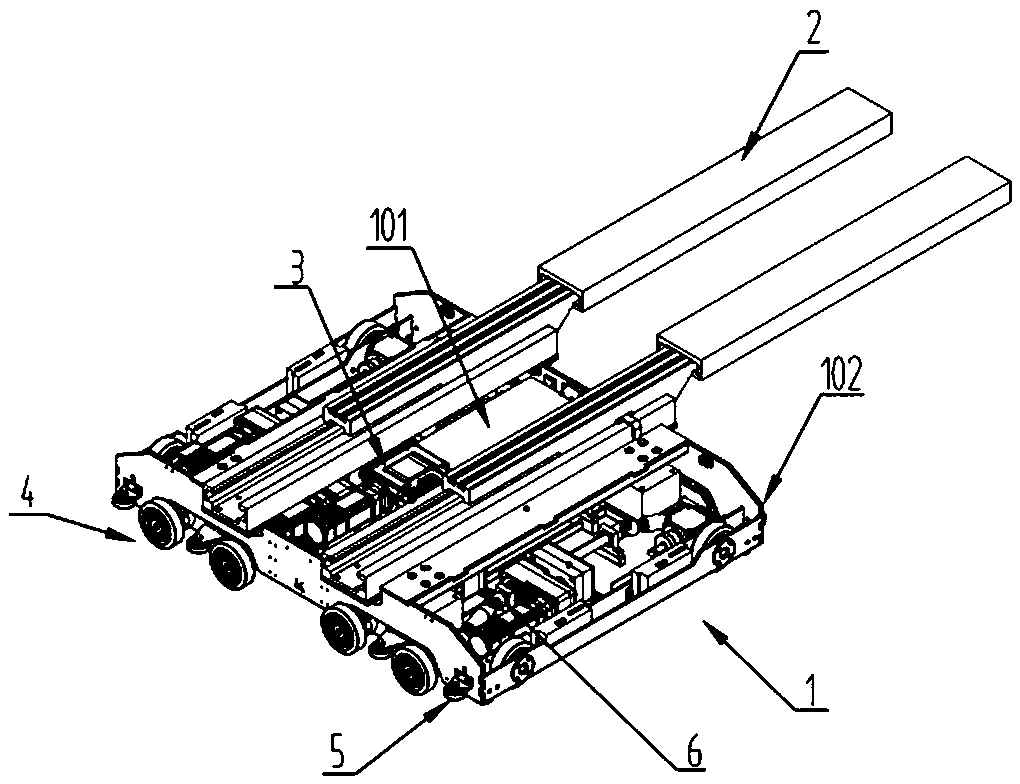
[0027] see figure 1 , in the embodiment of the present invention, a low-energy-consumption fork-type four-way shuttle vehicle includes a car body 1, telescopic forks 2 and road wheels 4, and several road wheels 4 are installed around the car body 1. To realize four-way movement, the present embodiment divides the road wheels 4 into X direction road wheels 401 and Y direction road wheels 402, which are respectively used to realize the forward or backward movement of the X direction and the Y direction, and the road wheels 4 are installed in the vehicle body 1 The walking mechanism 6 is driven to rotate, and the top of the car body 1 is equipped with a telescopic fork 2. Of course, the car body 1 is also equipped with a jacking mechanism 3 for driving the telescopic fork 2 to move up and down. The action of picking up goods can be realized by motor drive. Specifically, the mode of adding a motor through a screw rod belongs to the prior art, and redundant narration is not perform...
Embodiment 2
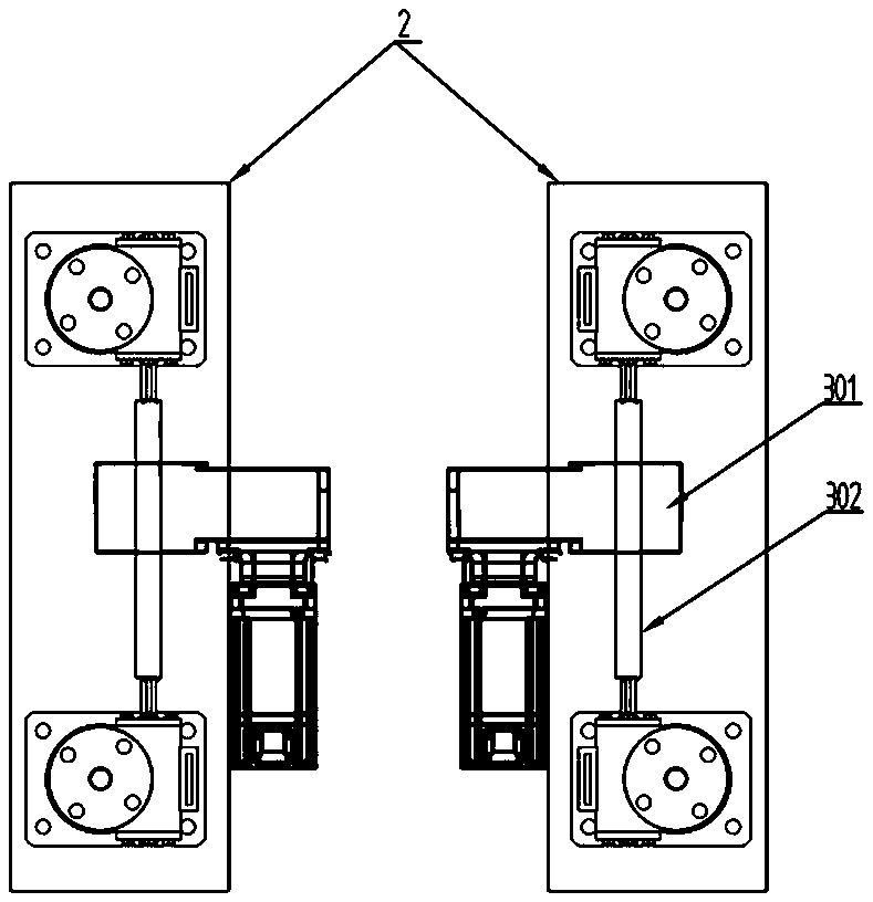
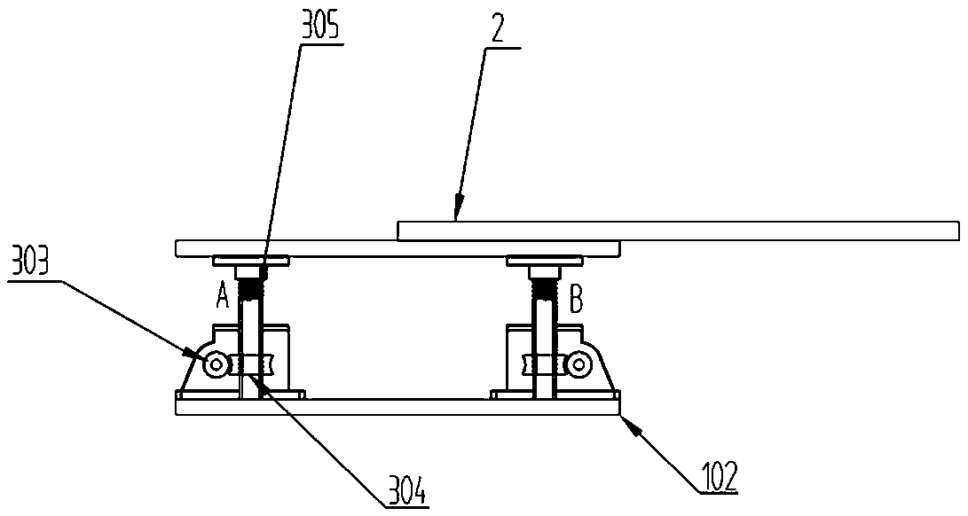
[0031] see Figure 2~3 , this embodiment is mainly to further explain the structure of the jacking mechanism 3. Specifically, the jacking mechanism 3 includes a jacking motor 301, a worm 303 and a worm wheel 304, and the jacking motor 301 is installed on the lower body 102 Inside, the output end of the jacking motor 301 is connected with the transmission shaft 302. In order to increase the torque, a reducer can also be installed between the jacking motor 301 and the transmission shaft 302. The end of the transmission shaft 302 is connected with a worm 303, and the worm 303 and The worm gear 304 is meshed and driven, and the worm gear 304 is fixed on the outside of the housing, and a screw 305 is installed in the housing, that is, the housing is provided with a thread that cooperates with the screw 305 for transmission. When the jacking motor 301 outputs power, the thread The screw rod 305 can move up and down due to the function of the screw rod 305, and the top of the screw r...
Embodiment 3
[0034] see Figure 4, this embodiment is to further explain the structure of the traveling mechanism 6, specifically, the traveling mechanism 6 includes a traveling motor 601, an output shaft 603, an X-direction driving shaft 606, a Y-direction driving shaft 607 and a bevel gear transmission box 608 , the traveling motor 601 is installed in the lower body 102, the output end of the traveling motor 601 is connected with an output shaft 603, in order to increase the torque, a speed reducer can also be installed between the traveling motor 601 and the output shaft 603, and the two ends of the output shaft 603 The two ends of the output shaft 603 are connected with the X-direction drive shaft 606, and the X-direction travel wheel 401 is installed on the X-direction drive shaft 606, and the output shaft 603 is also fixed with The driving gear 602 (the number of the driving gear 602 in the figure is one, and two can be added in actual application to respectively drive the rotation o...
PUM
 Abstract
Description
Claims
Application Information
 - R&D
- Intellectual Property
- Life Sciences
- Materials
- Tech Scout
- Unparalleled Data Quality
- Higher Quality Content
- 60% Fewer Hallucinations
Browse by: Latest US Patents, China's latest patents, Technical Efficacy Thesaurus, Application Domain, Technology Topic, Popular Technical Reports.
© 2025 PatSnap. All rights reserved.Legal|Privacy policy|Modern Slavery Act Transparency Statement|Sitemap|About US| Contact US: help@patsnap.com


