Draining structure

A technology of drainage structure and parapet wall, applied in the direction of roof drainage, building structure, roof, etc., can solve the problem that the width of the drainage ditch cannot meet the drainage requirements, the angle between the connecting rods of the support nodes is too much, and it is difficult to realize the longitudinal slope of the drainage ditch. and other problems, to achieve the effect of saving steel consumption, less connecting rods, and large width

Pending Publication Date: 2018-12-14
CHINA ENFI ENGINEERING CORPORATION
View PDF0 Cites 1 Cited by
  • Summary
  • Abstract
  • Description
  • Claims
  • Application Information

AI Technical Summary

Problems solved by technology

[0002] In the existing network frame and drainage structure, the network frame is often made into a shape whose upper and lower chord plane dimensions are not smaller than the lower chord plane size, and the top surface of the gutter support beam is higher than or equal to the upper chord plane of the grid frame, and the width of the gutter is limited by the support ball. The distance between the parapet and the parapet is limited. The distance between the parapet and the ball bearing is limited by the size of the column section. When the distance between the parapet and the ball joint is small, the width of the drainage ditch cannot meet the drainage requirements
The depth of the drainage ditch is limited by the total height of the support, main purlin, and secondary purlin. When the total height of the support, main purlin, and secondary purlin is small, it is difficult to achieve a longitudinal slope along the drainage ditch
The size of the upper chord plane of the grid frame is not smaller than the size of the lower chord plane, too many rods connected to the support nodes and the included angle is small, resulting in a large diameter of the support ball joints

Method used


Image

  • Draining structure
  • Draining structure
  • Draining structure

Examples


Embodiment 1

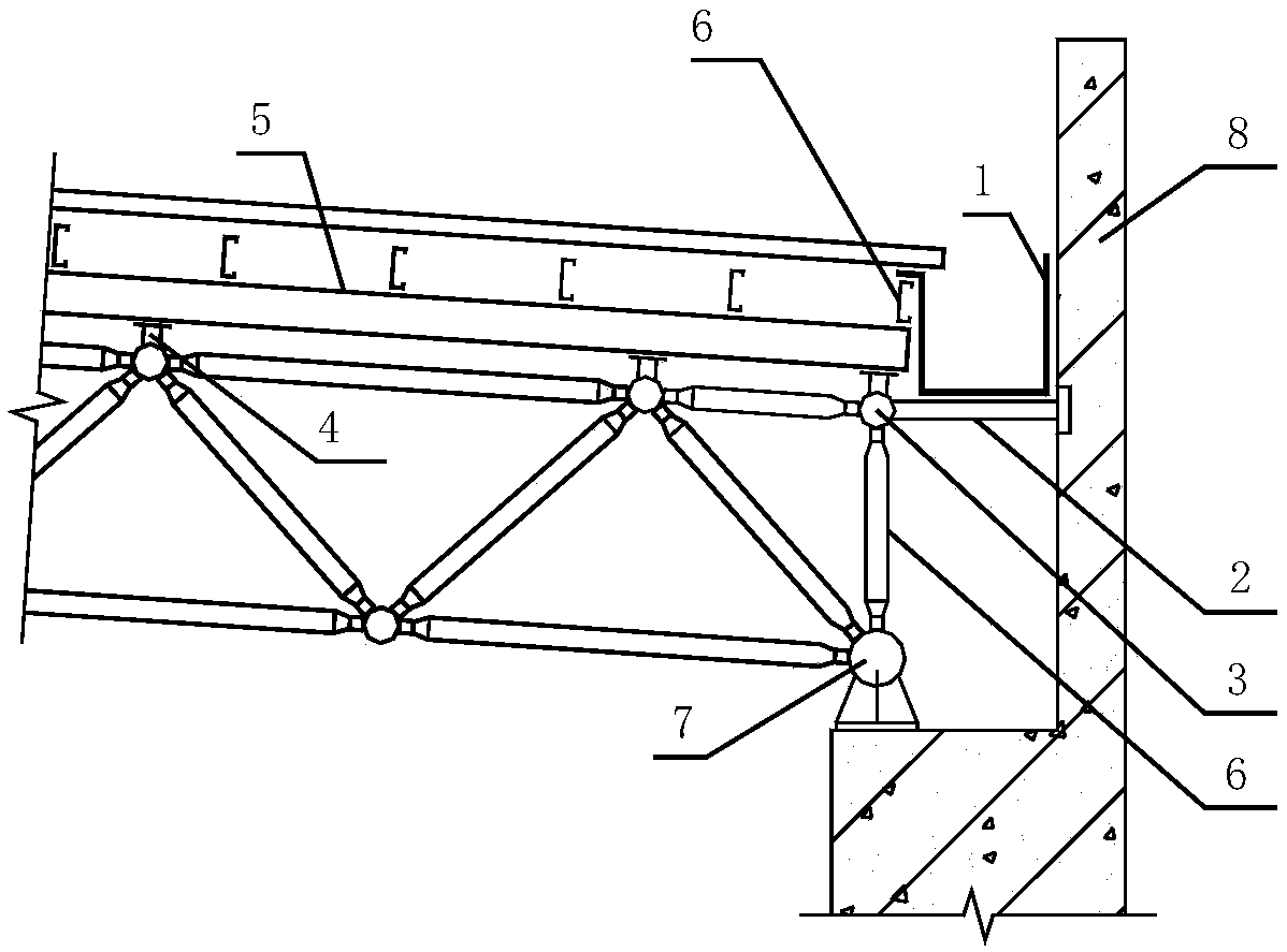
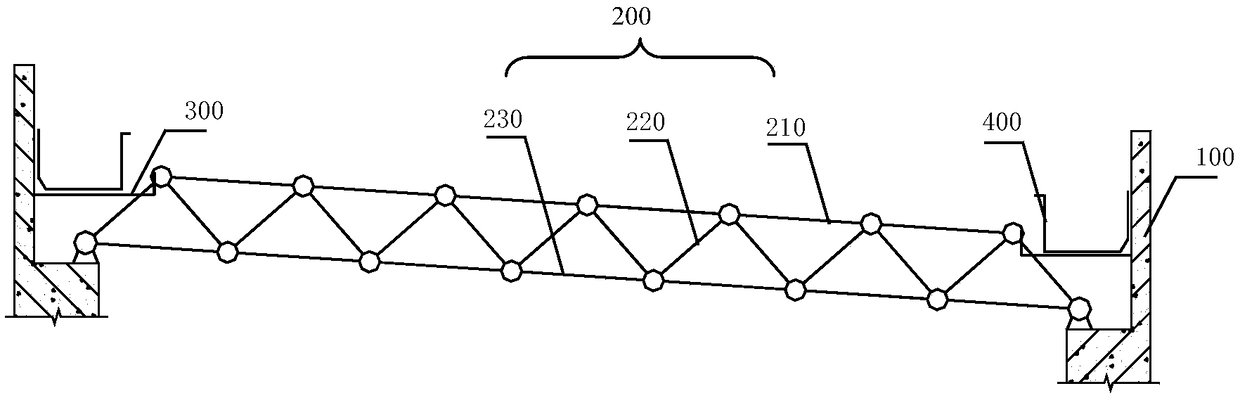
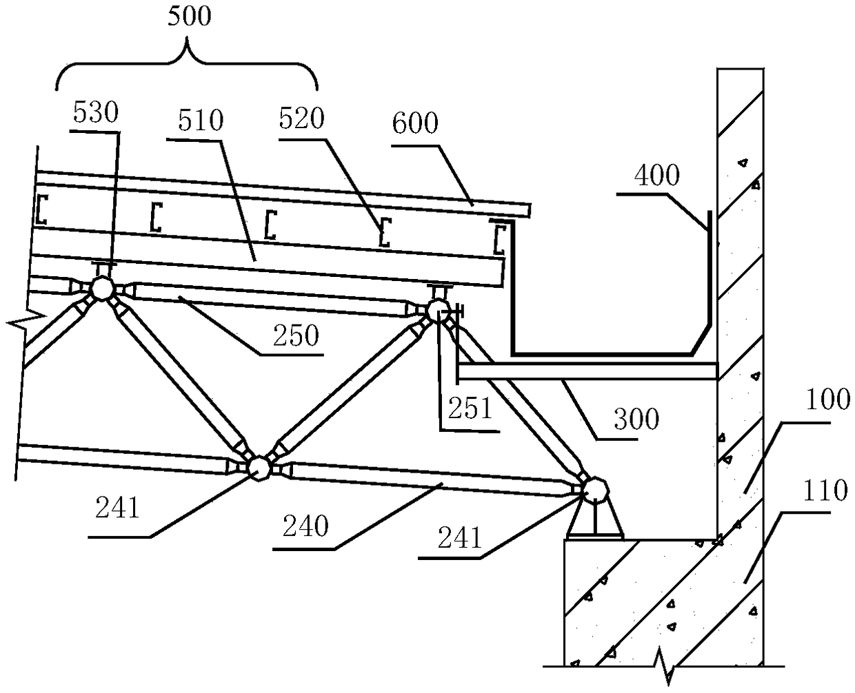
[0069] A drainage structure with a structure such as Figure 2-5 As shown, the size of the upper chord planar grid components of the grid frame is smaller than the size of the lower chord plane grid components, the number of ball nodes on the upper string string of the grid frame is smaller than the number of ball nodes on the lower string string of the grid frame, and the cross section of the grid frame is a trapezoid with a small top and a large bottom. Connect a gutter support beam between the first volleyball node near the parapet on the upper chord plane and the parapet. One end of the support beam is fixed on the first volleyball node of the upper chord plane grid assembly near the parapet by hanging the steel plate, and the other end is fixed on the parapet wall by the steel plate through expansion bolts. The height of the support beam is between the upper and lower chord plane grid components between. The gutter is located on the supporting beam, and the gutter is mad...


PUM


Abstract

The invention discloses a draining structure. The draining structure comprises parapets, a space truss, support beams and drainage channels; the space truss is formed by connecting a top-chord rod member, a bottom-chord rod member and diagonal bracing rods, and each diagonal bracing rod neighbor to the parapet of the space truss is further and further from the parapet from bottom to top gradually;one end of each support beam is connected with the corresponding parapet, and the other end of the support beam is connected to the top end close to the parapet of the space truss; and each drainagechannel is positioned in one corresponding support beam. Thus, the length of the support beam is not limited by the distance between the parapet and a ball joint of bearer, the support beam can be longer, the width of the drainage channel in the support beam can be also increased, and the wider the drainage channels are, the larger the draining flow is.

Description

technical field [0001] The invention relates to the field of civil engineering, in particular to drainage structures. Background technique [0002] In the existing network frame and drainage structure, the network frame is often made into a shape whose upper and lower chord plane dimensions are not smaller than the lower chord plane size, and the top surface of the gutter support beam is higher than or equal to the upper chord plane of the grid frame, and the width of the gutter is limited by the support ball. The distance between the parapet and the parapet is limited, and the distance between the parapet and the ball bearing is limited by the size of the column section. When the distance between the parapet and the ball joint is small, the width of the drainage ditch cannot meet the drainage requirements. The depth of the drainage ditch is limited by the total height of the support, main purlin, and secondary purlin. When the total height of the support, main purlin, and s...

Claims


Application Information

Patent Timeline
Patent Type & Authority Applications(China)
IPC IPC(8): E04D13/04E04D13/064E04B1/19
CPCE04D13/04E04B1/19E04D13/064
Inventor 于德广陈歌
Owner CHINA ENFI ENGINEERING CORPORATION
Why Eureka
Try Eureka