Combined winnower cooling system and using method thereof

A cooling system and combined technology, applied in the direction of engine cooling, coolant flow control, engine components, etc., can solve the problems of high energy consumption, poor cooling effect, airflow dead zone, etc., and achieve low energy consumption and easy operation. , to avoid the effect of excessive energy consumption

Pending Publication Date: 2018-12-14
DONGFENG COMML VEHICLE CO LTD
View PDF10 Cites 2 Cited by
  • Summary
  • Abstract
  • Description
  • Claims
  • Application Information

AI Technical Summary

Problems solved by technology

[0008] The purpose of the present invention is to overcome the defects and problems of existing airflow dead zone, high energy consumption and poor cooling effect in the prior art, and provide a kind of airflow dead zone, low energy consumption and good cooling effect. Combined fan vehicle cooling system and its application method

Method used


Image

  • Combined winnower cooling system and using method thereof
  • Combined winnower cooling system and using method thereof

Examples


Embodiment 1

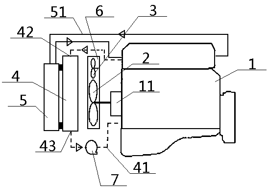
[0050] see Figure 1 to Figure 2 , a combined fan vehicle cooling system, including an engine 1, a conventional fan 2, a radiator 4 and an intercooler 5, the top and bottom of the radiator 4 are connected to the engine 1 through a waterway 41, and in the waterway 41 The flow direction of the coolant in the radiator 4 is from top to bottom, a conventional fan 2 is arranged between the inner side of the radiator 4 and the engine 1, the top of the engine 1 is connected with the intercooler 5 through the air passage 51, and the middle Cooler 5 is arranged on the outside of radiator 4; Described combined fan vehicle cooling system also includes electronic fan 3, and described electronic fan 3 is positioned between radiator 4 and engine 1, and electronic fan 3, conventional fan 2 are all connected with The inner side of the radiator 4 is directly opposite, and the electronic fan 3 is located above or below the conventional fan 2 . Preferably, the electronic fan 3 is located at the ...

Embodiment 2

[0056] Basic content is the same as embodiment 1, the difference is:

[0057] The electronic fan 3 is arranged near the coolant inlet 42 or the coolant outlet 43 of the radiator 4 .

Embodiment 3

[0059] Basic content is the same as embodiment 1, the difference is:

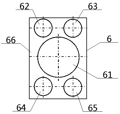
[0060] The combined fan vehicle cooling system also includes a windshield 6, the windshield 6 is located between the radiator 4 and the engine 1, and the cover surface 66 of the windshield 6 is provided with a central hole 61 and around it. The upper left oblique hole 62, the upper right oblique hole 63, the lower left oblique hole 64, and the lower right oblique hole 65 are provided. The fan blade of the electronic fan 3 is arranged in the corner hole 63 , the left lower oblique hole 64 or the right lower oblique hole 65 . The side enclosure of the windshield 6 is connected to the shell of the radiator 4 through bolts, and the electronic fan 3 is connected to the upper left oblique hole 62, the upper right oblique hole 63, the lower left oblique hole 64 or the lower right oblique hole through the bracket. The hole 65 is connected, and the conventional fan 2 is connected with the pulley 11 of the engine 1 ...


PUM


Abstract

A combined winnower cooling system comprises an engine, a conventional fan, an electronic fan, a radiator and an intercooler; the top end and the bottom end of the radiator are connected with the engine through waterways; the conventional fan and the electronic fan are arranged between the inner side of the radiator and the engine; the top of the engine is connected with the intercooler through agas path; the electronic fan is located above or below the conventional fan and preferably located at the upper left corner or the upper right corner or the lower left corner or the lower right cornerof the conventional fan; a fan guard for mounting of the conventional fan and the electronic fan is arranged between the radiator and the engine. During usage, three control strategies of natural aircooling, double cooling and triple cooling are adopted according to different engine water outlet temperatures. The combined winnower cooling system of the design is low in energy consumption, good in cooling effect, free of airflow dead zone, easy to operate, high in adaptability and wide in application range.

Description

technical field [0001] The invention relates to a vehicle cooling system, in particular to a combined fan vehicle cooling system and a method for using the same, which is particularly suitable for eliminating airflow dead zones, reducing energy consumption, and improving cooling effects. Background technique [0002] The existing vehicle cooling system adopts the working mode that the radiator is equipped with an electronically controlled silicon oil clutch. However, it is not easy to choose the size of the fan that matches the radiator. If the size of the fan is too large, the energy consumption of the fan will increase; if the size of the fan is too small, there may be a dead zone of airflow for the radiator, which will affect the working efficiency of the cooling system. [0003] The authorized announcement number is CN207297138U, and the utility model patent with the authorized announcement date on May 1, 2018 discloses a high and low temperature cooling system for a hea...

Claims


Application Information

Patent Timeline
Patent Type & Authority Applications(China)
IPC IPC(8): F01P5/04F01P7/08F01P7/04F01P5/06F01P11/10
CPCF01P5/04F01P5/06F01P7/026F01P7/048F01P7/08F01P11/10F01P2005/046F01P2005/025F01P2060/02
Inventor 贾李水李建华潘亮
Owner DONGFENG COMML VEHICLE CO LTD
Why Eureka
Try Eureka