Linearity calibration method of small depth-of-field linear frequency-modulated continues wave radar

A frequency-modulated continuous wave and depth-of-field linear technology, applied in the field of testing, can solve problems such as increasing system complexity, restricting resolution, and deteriorating the stability of radar work, improving calibration accuracy, simplifying calibration steps, and reducing requirements.

Active Publication Date: 2018-12-14
BEIJING INSTITUTE OF TECHNOLOGYGY
View PDF3 Cites 8 Cited by
  • Summary
  • Abstract
  • Description
  • Claims
  • Application Information

AI Technical Summary

Problems solved by technology

The method of direct digital frequency synthesis can achieve high linearity with the help of digital devices, but its transmission bandwidth and frequency conversion speed are limited by digital devices, which restricts the resolution of radar range detection
The pre-distortion voltage-controlled oscillator signal control method improves the frequency linearity of the voltage-controlled oscillator by feeding back the compensation voltage, thereby improving the linearity of the entire radar, but this method increases the complexity of the system
Moreover, the hardware-based linearity calibration method is easily affected by external factors such as temperature, which deteriorates the working stability of the radar.

Method used


Image

  • Linearity calibration method of small depth-of-field linear frequency-modulated continues wave radar
  • Linearity calibration method of small depth-of-field linear frequency-modulated continues wave radar
  • Linearity calibration method of small depth-of-field linear frequency-modulated continues wave radar

Examples


Embodiment Construction

[0021] The present invention will be described in detail below with reference to the accompanying drawings and examples.

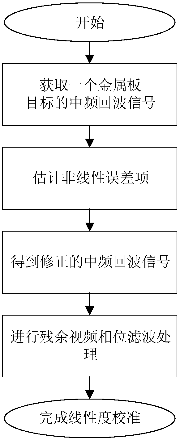
[0022] The present invention first estimates the nonlinear error based on the echo signal of a metal plate target, and then completes the nonlinear calibration of all target intermediate frequency echoes in the upward distance in real time, accurately and effectively according to the estimation result. Such as figure 1 As shown, it specifically includes the following steps:

[0023] Step 1. Obtain an intermediate frequency echo signal S of a metal plate target b '(n);

[0024] Place a metal plate target with strong reflectivity within the depth of field range of the linear frequency-modulated continuous wave radar with small depth of field, and record the intermediate frequency echo signal S of this target b '(n), which can be expressed as

[0025]

[0026]

[0027] Where n is a discrete time, rect(n) represents the time window, T is the frequenc...


PUM


Abstract

The invention discloses a linearity calibration method of a small depth-of-field linear frequency-modulated continues wave radar. The linearity calibration method comprises the following steps of 1, acquiring a medium-frequency echo signal S'b(n) of a metal plate target; 2, performing Fourier conversion and benchmark removal processing on the S'b(n) according to a non-linear effect of each devicein the radar system so as to obtain a phase jittering error c(n, Tau) caused by non-uniform linearity, and accumulating the phase jittering error c(n, Tau) to complete estimation of a non-linear erroritem Xi (n, Tau); 3, correcting a medium-frequency echo signal Sb(n) of a tested target to be calibrated according to the non-linear error item Xi (n, Tau) so as to obtain a corrected medium-frequency echo signal Sb2(n); and 4, calibrating the corrected medium-frequency echo signal Sb2(n) to obtain a medium-frequency echo signal Sb4(n), and completing linearity calibration. By the linearity calibration method, non-linear calibration of medium-frequency echoes of all targets in a distance direction can be accurately and effectively completed, and the detection resolution and the detection capability of the radar distance direction are improved.

Description

technical field [0001] The invention relates to the technical field of testing, in particular to a linearity calibration method of a linear frequency modulation continuous wave radar with a small depth of field. Background technique [0002] Linear frequency modulation continuous wave radar is a continuous wave radar using linear frequency modulation technology (LFM), which has the characteristics of low peak transmit power, large time-bandwidth product, no ambiguity in distance measurement, and high ranging resolution. The small depth-of-field LFM continuous wave radar system, which adopts quasi-optical focusing and other beam focusing forms, is widely used in the fields of human body security inspection and non-destructive testing because of its high lateral resolution. [0003] Linearity is an important indicator of chirp continuous wave radar, which describes the linearity of frequency modulation in the effective frequency band. When the linearity of the linear frequenc...

Claims


Application Information

Patent Timeline
Patent Type & Authority Applications(China)
IPC IPC(8): G01S7/40
CPCG01S7/40
Inventor 胡伟东李雅德司炜康刘芫喽吕昕
Owner BEIJING INSTITUTE OF TECHNOLOGYGY
Why Eureka
Try Eureka