Broadband radar three-dimensional interference measurement cone target fretting parameter estimation method

A broadband radar and interferometry technology, applied in the radar field, can solve problems such as coordinate distortion, target micro-Doppler analysis fuzzy, limited application of cone target geometric motion parameter estimation, etc., to achieve the effect of solving imaging distortion

Inactive Publication Date: 2018-12-14
XIDIAN UNIV +1
View PDF3 Cites 10 Cited by
  • Summary
  • Abstract
  • Description
  • Claims
  • Application Information

AI Technical Summary

Problems solved by technology

[0003] The micro-movement of the cone target is carried out in three-dimensional space, and the instantaneous position of the key scattering center contains rich geometric information of the cone target motion, which provides the basis for the estimation of the micro-motion parameters of the cone target by three-dimensional interferometry; considering the practical application, the radar broadband waveform The working pulse repetition frequency is usually hundreds or even tens of Hz, and there will be blurring and other processing problems in the micro-Doppler analysis of the target, and the target will inevitably deviate from the electric axis in practice, that is, in the case of squint, the traditional interferometry algorithm re- The three-dimensional coordinates of the cone target will be distorted, and the application of the geometric motion parameter estimation of the cone target is limited

Method used


Image

  • Broadband radar three-dimensional interference measurement cone target fretting parameter estimation method
  • Broadband radar three-dimensional interference measurement cone target fretting parameter estimation method
  • Broadband radar three-dimensional interference measurement cone target fretting parameter estimation method

Examples


Embodiment Construction

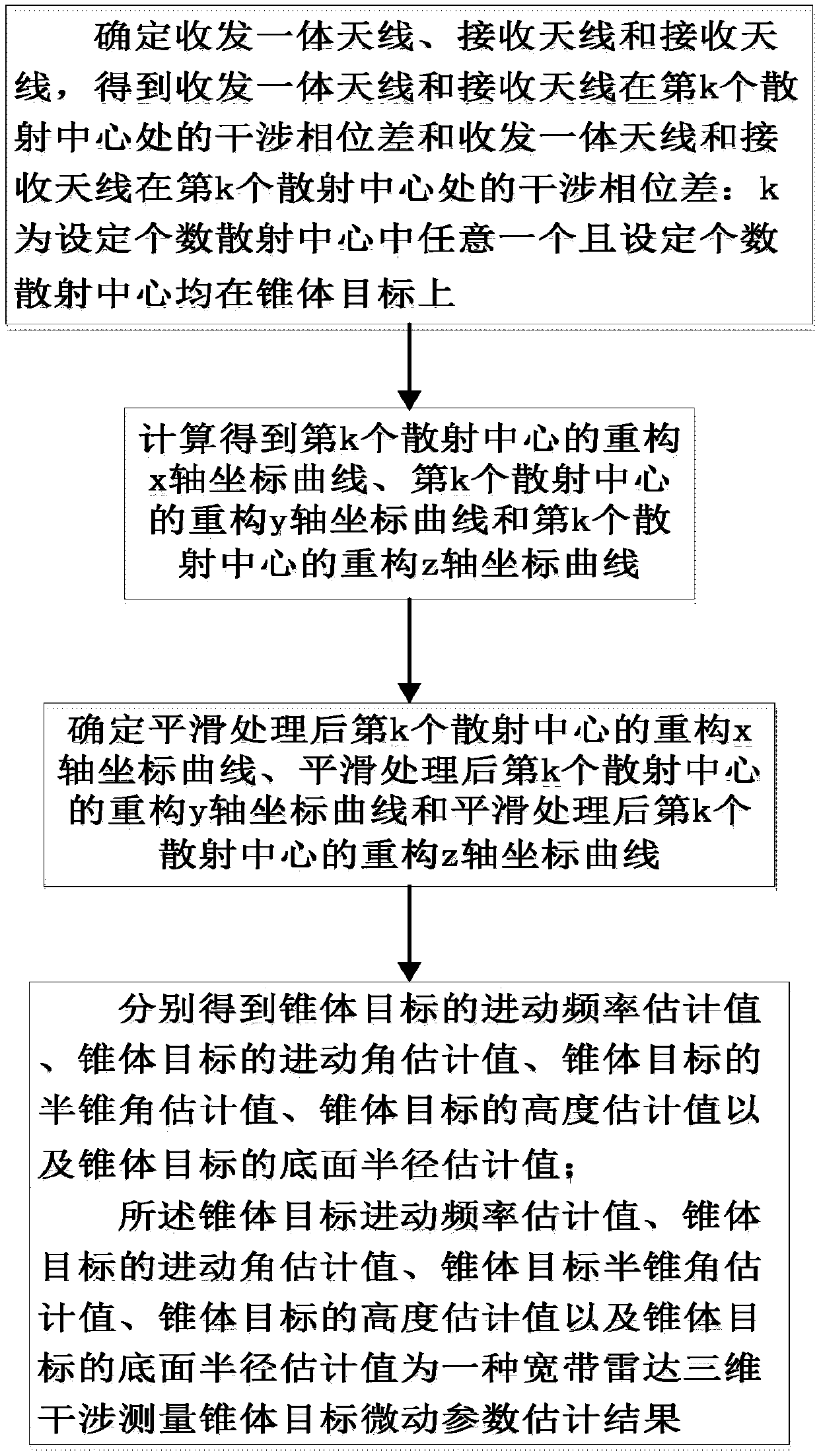
[0034] refer to figure 1 , is a flow chart of a method for estimating micro-motion parameters of a wideband radar three-dimensional interferometry cone target of the present invention; wherein the method for estimating micro-motion parameters of a cone target in three-dimensional broadband radar interferometry comprises the following steps:

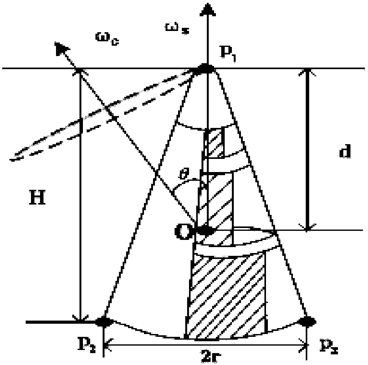
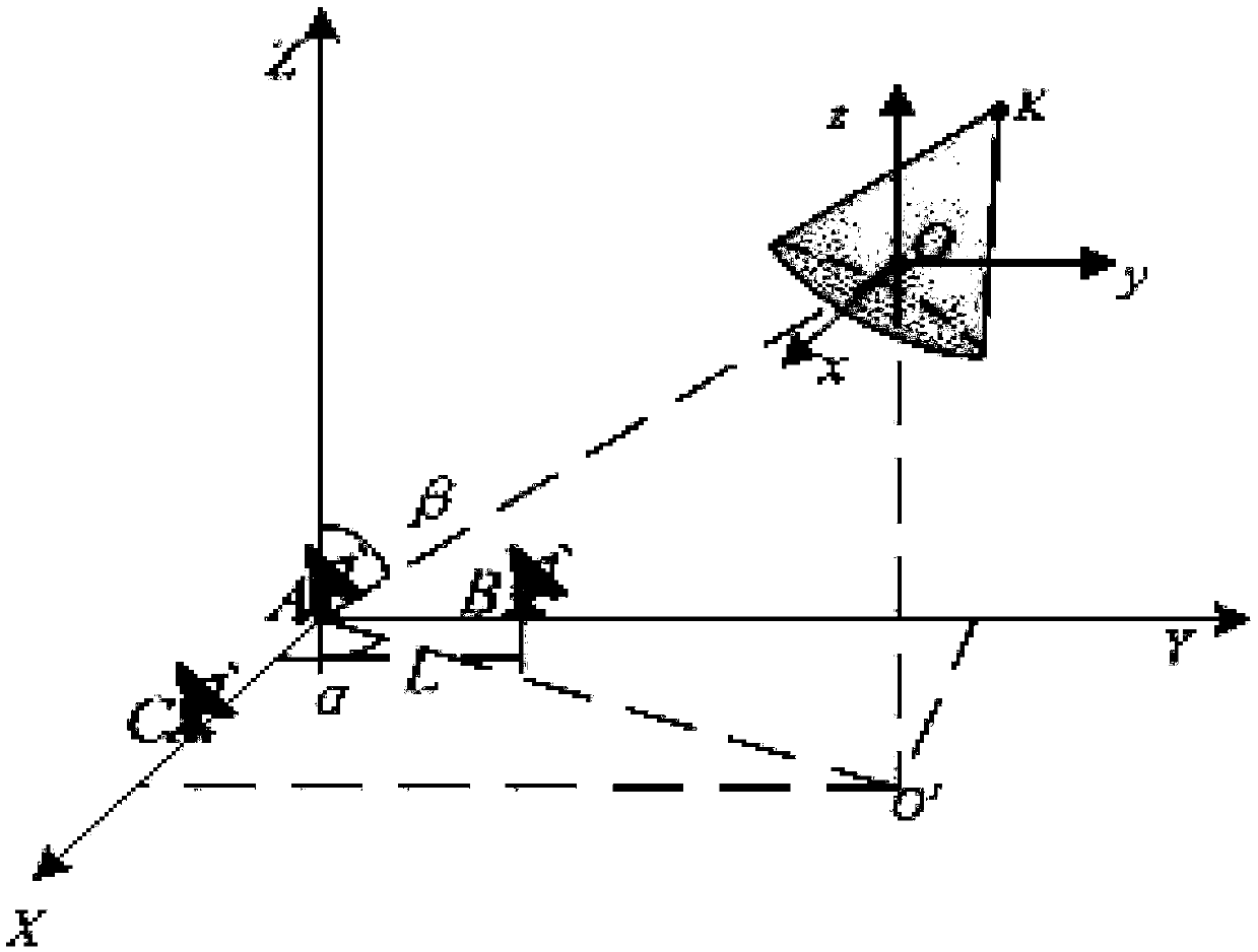
[0035] Step 1, establish the cone target precession model, and obtain t m The echo signal S of the kth scattering center in the fast time frequency domain-slow time received by the integrated transceiver antenna A at all times Adk (f,t m ), t m The echo signal S of the kth scattering center received by the receiving antenna B in the fast time frequency domain-slow time Bdk (f,t m ) and t m The echo signal S of the kth scattering center received by the receiving antenna C in the fast time frequency domain-slow time Cdk (f,t m ), and perform interference processing on the received echo signals of the antenna pairs on the two baseline...


PUM


Abstract

The invention discloses a broadband radar three-dimensional interference measurement cone target fretting parameter estimation method. The method comprises steps that a transmitting-receiving integrated antenna A, a receiving antenna B, and a receiving antenna C are determined, and an interference phase difference between the transmitting-receiving integrated antenna A and the receiving antenna Bon a kth scattering center and the interference phase difference between the transmitting-receiving integrated antenna A and the receiving antenna C on the kth scattering center are acquired: k is anyone of a set number of scattering centers, which are disposed on a cone target; the reconstruction x axis coordinate curve of the kth scattering center after smoothing processing, and the reconstruction y axis coordinate curve of the kth scattering center after the smoothing processing, and the reconstruction z axis coordinate curve of the kth scattering center after the smoothing processing aredetermined, and then after the precession frequency estimated value <^>f<c> of the cone target, the angle of precession estimated value <^>Theta of the cone target, the half cone angle estimated value<^>Eta of the cone target, the height estimated value <^>H of the cone target, and the bottom surface radius estimated value <^>r of the cone target are acquired, a broadband radar three-dimensionalinterference measurement cone target fretting parameter estimated result is acquired.

Description

technical field [0001] The invention belongs to the technical field of radar, in particular to a method for estimating micro-motion parameters of a cone target in three-dimensional interferometric measurement of a broadband radar, which is suitable for robustly estimating the micro-motion and geometric parameters of the cone target. Background technique [0002] Ballistic missiles have become the dominant weapon in modern warfare, and the mid-flight of missiles is often accompanied by decoys. The fretting characteristics of cone targets such as warheads and decoys have obvious differences due to their different mass distributions. Therefore, the fretting parameters of cone targets are estimated It has become an important technology for cone target recognition in missile defense systems; with the continuous development of high-resolution radar technology and modern signal processing technology, the estimation of micro-motion parameters of cone targets has gradually developed f...

Claims


Application Information

Patent Timeline
Patent Type & Authority Applications(China)
IPC IPC(8): G01S7/41
CPCG01S7/41
Inventor 张磊魏嘉琪刘宏伟周叶剑
Owner XIDIAN UNIV
Why Eureka
Try Eureka