Liquid crystal condensation micromirror array driven and controlled on the basis of frequency signal, and preparation method thereof

A technology of condensing micromirrors and frequency signals, applied in optics, nonlinear optics, instruments, etc., can solve the problems of large size of voltage signal output device, poor use efficiency of liquid crystal condensing micromirrors, and difficulty in miniaturization/miniaturization. , to achieve the effect of simple and flexible control mode, low power consumption and smart structure

Inactive Publication Date: 2018-12-14
NANJING OPY ELECTRONICS TECH CO LTD
View PDF4 Cites 7 Cited by
  • Summary
  • Abstract
  • Description
  • Claims
  • Application Information

AI Technical Summary

Problems solved by technology

[0004] In view of the above defects or improvement needs of the prior art, the present invention provides a frequency signal-based liquid crystal concentrating micromirror array and its preparation method, the purpose of which is to solve the problem of existing conventional electronically controlled liquid crystal concentrating micromirror In the process of regulating its concentrating efficiency, because the loaded voltage signal changes in a wide range, the generation, modulation, fine control of the voltage signal, the effective coupling of the voltage signal and the liquid crystal concentrating micromirror array, power consumption, Liquid crystal concentrating micromirror arrays have high technical requirements such as effective heat dissipation, and voltage signal output devices have large dimensions, complex structures, high costs, and are difficult to be small / miniaturized, and difficult to integrate with liquid crystal concentrating micromirror arrays. Technical problems, and technical problems that easily lead to poor performance of liquid crystal concentrating micromirrors and small application range

Method used


Image

  • Liquid crystal condensation micromirror array driven and controlled on the basis of frequency signal, and preparation method thereof
  • Liquid crystal condensation micromirror array driven and controlled on the basis of frequency signal, and preparation method thereof
  • Liquid crystal condensation micromirror array driven and controlled on the basis of frequency signal, and preparation method thereof

Examples


Embodiment Construction

[0041] In order to make the object, technical solution and advantages of the present invention clearer, the present invention will be further described in detail below in conjunction with the accompanying drawings and embodiments. It should be understood that the specific embodiments described here are only used to explain the present invention, not to limit the present invention. In addition, the technical features involved in the various embodiments of the present invention described below can be combined with each other as long as they do not constitute a conflict with each other.
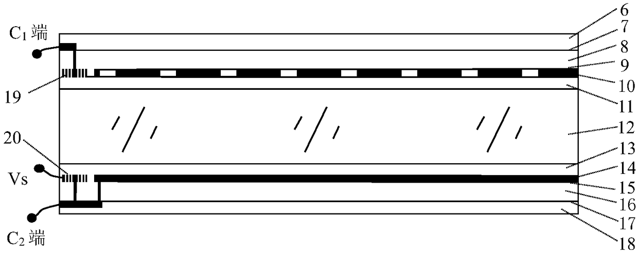
[0042] The basic idea of ​​the present invention is that by loading a voltage signal with an adjustable frequency and a maximum mean square amplitude of only a few volts on the liquid crystal concentrating micromirror array, the voltage signal directly acts on the electrode connected to the common electrode and arranged at its edge. The second micro-coil group, the first micro-coil group arrange...


PUM

PropertyMeasurementUnit
thicknessaaaaaaaaaa
thicknessaaaaaaaaaa
thicknessaaaaaaaaaa

Abstract

The invention discloses a liquid crystal condensation micromirror array driven and controlled on the basis of a frequency signal. A voltage signal is loaded on the liquid crystal condensation micromirror array, wherein the frequency of the voltage signal is adjustable, and the maximum mean square amplitude value of the voltage signal is only about few volts; and on the basis of a signal inductionand voltage amplification function between electric insulation micro-coils, specific intensity required by the micromirror array and a spatial distribution control electric field or magnetic field areconstructed to finish a condensation operation for driving and controlling the liquid crystal condensation micromirror array on the basis of the frequency signal. The liquid crystal condensation micromirror array has the advantages that the condensation efficiency of the liquid crystal condensation micromirror array is elaborately regulated, power consumption is low, and a frequency voltage regulation device and the liquid crystal condensation micromirror are integrated so as to be easily coupled with other functionally optical, photoelectric, light-emitting and electronics structures.

Description

technical field [0001] The invention belongs to the technical field of optical lenses, and more specifically relates to a liquid crystal concentrating micromirror array driven and controlled by a frequency signal and a preparation method thereof. Background technique [0002] For conventional electronically controlled liquid crystal concentrating micromirror arrays working in the visible or infrared spectrum, by loading a voltage signal of a specific frequency on the control electrodes in the micromirrors, an arrayed non-magnetic array is generated between the control electrodes at micrometer intervals. The uniform spatial electric field or magnetic field drives the liquid crystal material arranged between the control electrodes to produce a specific spatial distribution pattern in an array, so that the liquid crystal material presents a refractive index distribution mode with arrayed light-gathering performance. By directly modulating the mean square amplitude of the loaded...

Claims


Application Information

Patent Timeline
Patent Type & Authority Applications(China)
IPC IPC(8): G02F1/13G02F1/1333G02F1/1335G02F1/1337G02F1/1343G02F1/29
CPCG02F1/1313G02F1/1333G02F1/1335G02F1/1337G02F1/1343G02F1/29
Inventor 张新宇张汤安苏
Owner NANJING OPY ELECTRONICS TECH CO LTD
Why Eureka
Try Eureka