Display panel, manufacturing method thereof, and display device

A technology for display panels and array substrates, applied in semiconductor/solid-state device manufacturing, electrical components, electric solid-state devices, etc., can solve problems such as poor display of display panels, avoid poor display or display failure, improve bending strength and withstand Effect of drop impact strength

Active Publication Date: 2018-12-14
YUNGU GUAN TECH CO LTD
View PDF4 Cites 10 Cited by
  • Summary
  • Abstract
  • Description
  • Claims
  • Application Information

AI Technical Summary

Problems solved by technology

[0005] Based on this, it is necessary to provide a display panel, its manufacturing method, and a display device that improve the above-mentioned problems in view of the problem that the display panel in the existing design is prone to poor display when it is bent and withstands a drop impact.

Method used


Image

  • Display panel, manufacturing method thereof, and display device
  • Display panel, manufacturing method thereof, and display device
  • Display panel, manufacturing method thereof, and display device

Examples


Embodiment Construction

[0032] In order to facilitate the understanding of the present invention, the present invention will be described more fully below with reference to the associated drawings. Preferred embodiments of the invention are shown in the accompanying drawings. However, the present invention can be embodied in many different forms and is not limited to the embodiments described herein. On the contrary, these embodiments are provided to make the understanding of the disclosure of the present invention more thorough and comprehensive.

[0033] Unless otherwise defined, all technical and scientific terms used herein have the same meaning as commonly understood by one of ordinary skill in the technical field of the invention. The terms used herein in the description of the present invention are for the purpose of describing specific embodiments only, and are not intended to limit the present invention. As used herein, the term "and / or" includes any and all combinations of one or more of ...


PUM


Abstract

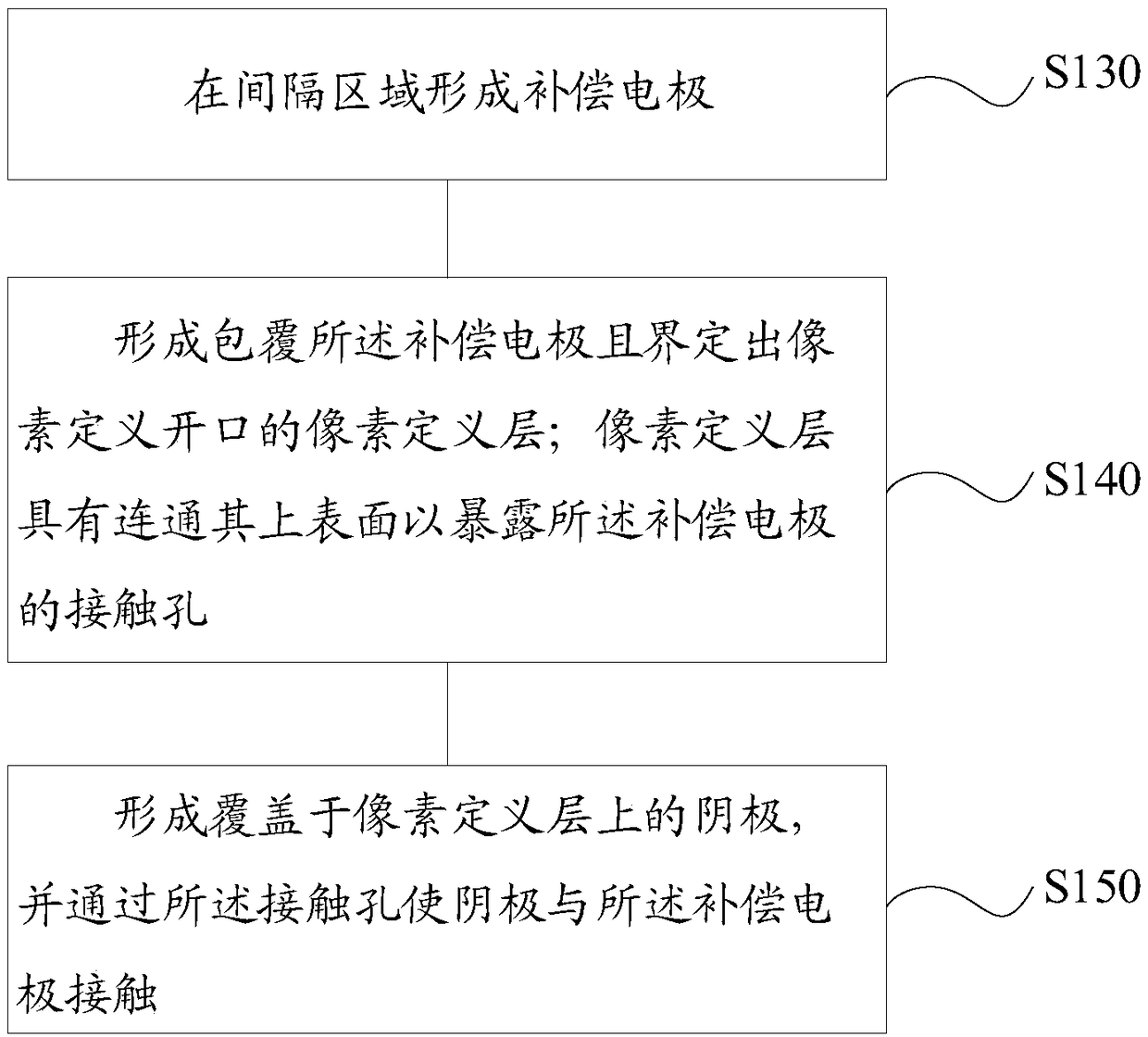
The invention relates to a display panel, comprising a pixel definition layer, a cathode and a compensation electrode. The pixel definition layer defines a plurality of pixel definition openings and aspacing area between the pixel definition openings. A cathode is overlaid on the pixel definition layer. The pixel definition layer is configured to cover the compensation electrode and has a contacthole communicating with an upper surface thereof so that the cathode contacts the compensation electrode through the contact hole. As that display panel is subject to drop impact or multiple bending,The thin film encapsulation layer is bent downward along the direction of the applied force, and the impact force is transmitted to the cathode layer. The compensation electrode and the cathode layeroverlap each other through the contact hole to form a three-dimensional three-dimensional network structure, which can support the cathode layer and disperse the impact stress, thereby preventing thecathode from breaking or being separated from the organic light-emitting unit. Thus, the bending strength and the impact strength against drop of the display panel are improved. Also provided are a method for manufacturing a display panel and a display device.

Description

technical field [0001] The present invention relates to the field of display technology, in particular to a display panel, a manufacturing method thereof, and a display device. Background technique [0002] With the development of technologies such as big data, cloud computing, and mobile Internet, human beings have entered the era of intelligence, including smart mobile communication terminals, wearable devices, and smart home devices, which have become an indispensable part of people's work and life. As an important window for human-computer interaction in the era of intelligence, display panels are also undergoing major changes. Organic light-emitting diode (Organic Light-Emitting Diode, OLED) display panel has the advantages of thin thickness, self-luminous performance, low power consumption, and good flexibility. Flat panel display device. [0003] In order to pursue a better visual experience and tactile experience, the requirements for the effective display area and...

Claims


Application Information

Patent Timeline
Patent Type & Authority Applications(China)
IPC IPC(8): H01L27/32H01L51/52
CPCH10K59/123H10K59/121H10K59/122H10K59/12H10K50/84H10K50/824H10K59/1315H10K71/00H10K59/1201
Inventor 王鑫楠刘如胜
Owner YUNGU GUAN TECH CO LTD
Why Eureka
Try Eureka