
Special-shaped barrel combined continuous ball mill

A ball mill and cylinder technology, which is applied in the field of special-shaped cylinder combined continuous ball mills, can solve problems such as poor grinding effect, and achieve the effects of less quantity, reduced rotation and improved grinding effect.

Inactive Publication Date: 2018-12-18
JINGDEZHEN CERAMIC INSTITUTE
View PDF5 Cites 2 Cited by
  • Summary
  • Abstract
  • Description
  • Claims
  • Application Information

AI Technical Summary

Problems solved by technology

The three chambers of the existing continuous ball mill are all cylindrical. Driven by the motor, the rotation is easy to produce a phenomenon of rotation, that is, the ground material continues to grind while the unground material continues to be ground, resulting in poor grinding effect.

Method used


Image

  • Special-shaped barrel combined continuous ball mill
  • Special-shaped barrel combined continuous ball mill
  • Special-shaped barrel combined continuous ball mill

Examples


Embodiment 1

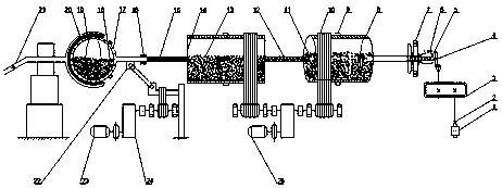
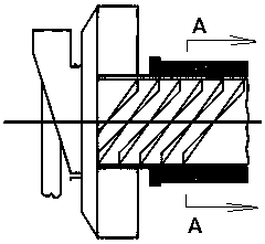
[0030] see figure 1 , figure 2 and image 3 , in the embodiment of the present invention, a special-shaped cylinder combined continuous ball mill, including a first motor 1, the first motor 1 is connected with the first reducer 3 through the coupling 2, the first reducer 3 is connected through the open cone The gear 4 is connected with the screw feeding device 5, and the screw feeding device 5 is connected with the cylinder crushing bin 8 through the feeding end cover 7, and the feeding end cover 7 plays a role of fixing the screw feeding device 5, and the cylindrical The crushing chamber 8 is provided with a crushing chamber grinding body 11 .

Embodiment 2

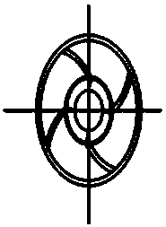
[0032] see figure 1 and Figure 4 , the cylindrical crushing bin 8 is connected to the coarse grinding bin 14 through the first filter screen 12, the cross section of the coarse grinding bin 14 is a regular octagon, and the cylindrical crushing bin 8 and the coarse grinding bin 14 are connected to the first coarse grinding bin 14 through the belt 10 The two motors 23 are connected, and the coarse grinding chamber 14 is provided with a coarse grinding chamber grinding body 13. The coarse grinding chamber 14 adopts a regular octagonal cylinder structure, and its cross section is a regular octagon instead of a circle, which can reduce the rotation to a certain extent. phenomenon, greatly improving the grinding effect; the first filter screen 12 can prevent the crushing chamber grinding body 13 and unground materials from entering the coarse grinding chamber 14 and control the rate at which the ground materials enter the coarse grinding chamber 14.

Embodiment 3

[0034] see figure 1 , the coarse grinding chamber 14 is connected with a plastic flexible hose 16 through the second filter screen 15, the second filter screen 15 can prevent the coarse grinding chamber grinding body 13 and unground material from entering the spherical fine grinding chamber 19 and control the completion of the grinding The rate at which the material enters the spherical fine grinding bin 19, the scalability of the plastic flexible hose 16 can ensure the normal movement of the spherical fine grinding bin 19 when it rotates up and down, left and right; the plastic scalable hose 16 is connected with the spherical fine grinding bin 19. The outer side of the spherical fine grinding chamber 19 is provided with a fine grinding chamber grinding body 18, and the spherical fine grinding chamber 19 is connected with the third motor 25 through the linkage mechanism 22 and the second reducer 24, and the linkage mechanism 22 is connected to the third motor Driven by 25, the...


PUM


Abstract

The invention relates to the technical field of ball mills, in particular to a special-shaped barrel combined continuous ball mill. The special-shaped barrel combined continuous ball mill comprises afirst motor; the first motor is connected with a first speed reducer through a coupling; the first speed reducer is connected with a spiral feeding device through an open bevel gear; the spiral feeding device is connected with a cylindrical smashing bin through a feeding end cover; a smashing bin grinder is arranged in the cylindrical smashing bin; the cylindrical smashing bin is connected with acoarse grinding bin through a first filter screen, and the cross section of the coarse grinding bin is regularly octagonal; and the cylindrical smashing bin and the coarse grinding bin are connected through a second motor through a belt. The special-shaped barrel combined continuous ball mill has the beneficial effects that the coarse grinding bin is of a regular octagon barrel structure, and thecross section of the coarse grinding bin is regularly octagonal instead of being round, so that the phenomenon of rotation is relieved to a certain extent and the grinding effect is greatly improved;and the first filter screen can prevent the smashing bin grinder and unground materials from entering the coarse grinding bin and can control the entry rate of ground materials into the coarse grinding bin.

Description

technical field [0001] The invention relates to the technical field of ball mills, in particular to a special-shaped cylindrical combined continuous ball mill. Background technique [0002] Ball mill is the key equipment for crushing materials after being crushed. It is widely used in cement, silicate products, new building materials, refractory materials, chemical fertilizers, non-ferrous metal beneficiation and glass ceramics and other production industries. Grindable materials are subjected to dry or wet grinding. [0003] The existing grinding processing equipment for ceramic raw materials is divided into intermittent ball mill and continuous ball mill. Due to the increase of temperature in the barrel of the continuous ball mill and the dynamic pulping, the viscosity of the slurry is reduced, thereby reducing the water consumption of ball milling materials. And spray drying evaporation, energy saving effect is obvious. The whole set of equipment adopts PLC control, whi...

Claims


Application Information

Patent Timeline
IPC IPC(8): B02C17/18B02C17/22
CPCB02C17/18B02C17/183B02C17/22
Inventor 吴南星郑琦邓立钧余冬玲方长福江竹亭廖达海汪伟王翔
Owner JINGDEZHEN CERAMIC INSTITUTE
Learn More