Edge grinding device and glass edge grinding method applicable to various shapes of glass

A glass and edging technology, which is applied in the direction of machine tools, grinding machines, grinding/polishing equipment, etc., which are suitable for grinding the edge of workpieces. Single and other problems, to reduce the steps of turning and handling, improve the efficiency of edging, and reduce the labor force

Active Publication Date: 2021-10-29
湖州精耕农机有限公司
View PDF8 Cites 0 Cited by
  • Summary
  • Abstract
  • Description
  • Claims
  • Application Information

AI Technical Summary

Problems solved by technology

[0003] With the rapid development of social industrialization, people's demand for glass output is increasing, and the demand for glass quality is constantly improving. Therefore, various automated glass edge grinding machines are constantly produced. The existing glass edge grinding devices are mainly made of It is composed of machine and transmission equipment. Through long-term production practice, it is found that the existing glass edging device has the following defects: the purpose of the existing glass edging device is relatively single, and it performs linear edging on one side of the glass. Among them, the shape of the glass is various. For example, the mirror is made of rectangular glass, the round table is made of round glass, and special-shaped glass is used in some furniture. The traditional edging device obviously cannot meet the requirements of production. Need; when edging glass, two more corners are needed for edging, so two processes are required to complete all edging; in general manual edging, the person controls the edging tool, the grinding wheel and the glass are in intermittent contact, and When using an edging machine for edging, the grinding wheel and the glass are always in contact, and the grinding wheel and the glass will not separate until the edging is completed. In this way, it is difficult to control the edging force and the amount of edging, and it is easy to cause the glass to break.

Method used


Image

  • Edge grinding device and glass edge grinding method applicable to various shapes of glass
  • Edge grinding device and glass edge grinding method applicable to various shapes of glass
  • Edge grinding device and glass edge grinding method applicable to various shapes of glass

Examples


Embodiment 1

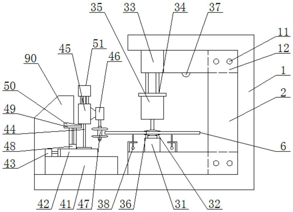
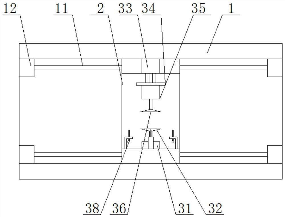
[0035] combined with figure 1 And attached figure 2 As shown, the present invention relates to a kind of edging device suitable for various shapes of glass, which includes a cabinet, a clamping mechanism, an edging mechanism and a control system, and the cabinet includes an outer casing 1 and a mobile base 2, The outer casing 1 is provided with guide columns 11 arranged horizontally and corresponding up and down. The two ends of the guide columns 11 are provided with a base driving device 12. The base driving device 12 adopts an oil cylinder. The mobile base 2 has a U-shaped structure. The seat 2 is arranged inside the outer casing 1 , the guide post 11 runs through the mobile base 2 , and the mobile base 2 is driven by the base driving device 12 so that it can move back and forth along the direction of the guide post 11 .

[0036]Described clamping mechanism comprises clamping cylinder 33, rotating disk 31 and rotating motor 35, and clamping cylinder 33 is fixed on the top ...

Embodiment 2

[0040] This embodiment is based on the attached Image 6 The circular glass edging shown is taken as an example, and the edging method using the glass edging machine described in Embodiment 1 is described. The steps include,

[0041] Step 1: Attach the Image 6 The shown glass 6 is placed on the turntable, and the glass 6 generates pressure to the surrounding measuring instruments 38, and the surrounding measuring instruments 38 send their respective pressure values ​​to the main control machine 90 for analysis, and the display screen of the main control machine 90 displays each Measure the pressure value of the instrument 38, and adjust the position of the glass 6 according to the pressure difference, so that the center of gravity of the glass 6 falls on the axis of the turntable 31, and the clamping cylinder 33 is controlled by the main control machine 90 to press down the rotating motor 35, so that the rotating motor The upper sucker 36 of 35 lower ends and the upper suck...

Embodiment 3

[0046] This embodiment is based on the attached Figure 7 The rectangular glass edging shown is taken as an example, and the edging method using the glass edging machine described in Embodiment 1 is described. The steps include,

[0047] Step 1: Attach the Figure 7 The shown glass 6 is placed on the turntable, and the glass 6 generates pressure to the surrounding measuring instruments 38, and the surrounding measuring instruments 38 send their respective pressure values ​​to the main control machine 90 for analysis, and the display screen of the main control machine 90 displays each Measure the pressure value of the instrument 38, and adjust the position of the glass 6 according to the pressure difference, so that the center of gravity of the glass 6 falls on the axis of the turntable 31, and the clamping cylinder 33 is controlled by the main control machine 90 to press down the rotating motor 35, so that the rotating motor The upper sucker 36 of 35 lower ends and the upper...


PUM


Abstract

The invention relates to an edging device and glass edging method suitable for various shapes of glass. The device includes a cabinet, a clamping mechanism, an edging mechanism and a control system. The clamping mechanism is installed inside the cabinet for clamping the glass. The left and right movement and rotation of the glass can be realized through the control system. The edging mechanism is used for edging the upper and lower corners and the outer ring of the glass at the same time, and the edging mechanism can move forward and backward through the control system. The edging mechanism It can also be realized to fluctuate up and down according to the law. The invention takes pictures of the glass through the camera, and models the glass, and the control system selects a suitable edging program according to the modeled structure, and then realizes the edging of multi-shaped glass by using one machine, reducing the equipment cost , and the edging device involved in the present invention simulates the way of manual edging, the edging effect is better, the automatic operation is adopted, and the efficiency is higher.

Description

technical field [0001] The invention relates to the field of glass product processing, in particular to an edging device suitable for various shapes of glass, and discloses a glass edging method using the edging device suitable for various shapes of glass. Background technique [0002] Glass edging machine is one of the earliest and most widely used mechanical equipment in glass deep processing equipment. Its main function is to smooth the glass and make some special shapes. The working process of the existing glass edging machine is as follows: the glass is transported to the grinding wheel assembly through the conveyor belt, and the grinding wheel assembly is driven by the moving carriage to contact the glass and perform edging according to the set cutting amount. After the edging is completed, it is switched to The other side is edging or enters the next process production line. [0003] With the rapid development of social industrialization, people's demand for glass ou...

Claims


Application Information

Patent Timeline
Patent Type & Authority Patents(China)
IPC IPC(8): B24B1/00B24B9/08
CPCB24B1/00B24B9/08
Inventor 潘景玮
Owner 湖州精耕农机有限公司
Why Eureka
Try Eureka