Multi-factor coupling passive control technology inhibiting blade tip clearance flow loss of radial flow turbine

A technology of coupling control and blade tip clearance, which is applied to engine components, machines/engines, and leakage prevention, etc., can solve the problems of radial turbine blade tip clearance flow structure types, low operating efficiency, and large gap flow loss, etc., to achieve Effects of suppression of interstitial flow loss, improvement of operating efficiency, and enhancement of working ability

Active Publication Date: 2018-12-18
INST OF ENGINEERING THERMOPHYSICS - CHINESE ACAD OF SCI
View PDF5 Cites 4 Cited by
  • Summary
  • Abstract
  • Description
  • Claims
  • Application Information

AI Technical Summary

Problems solved by technology

[0004] In order to solve the problems of many types of flow structures, large losses, and low operating efficiency in radial turbine blade tip clearances, the present invention discloses a multi-element coupling passive control technology for suppressing radial turbine blade tip clearance flow losses, which relates to radial flow turbines. Center, mixed flow and other types, this technology solves the problem of large gap flow loss in radial turbines, meets the needs of efficient operation of radial turbines, and promotes the application of radial turbines in high-efficiency operation systems. Features, has broad application prospects

Method used


Image

  • Multi-factor coupling passive control technology inhibiting blade tip clearance flow loss of radial flow turbine
  • Multi-factor coupling passive control technology inhibiting blade tip clearance flow loss of radial flow turbine
  • Multi-factor coupling passive control technology inhibiting blade tip clearance flow loss of radial flow turbine

Examples


Embodiment Construction

[0034] In order to make the object, technical solution and advantages of the present invention clearer, the present invention will be further described in detail below with reference to the accompanying drawings and examples.

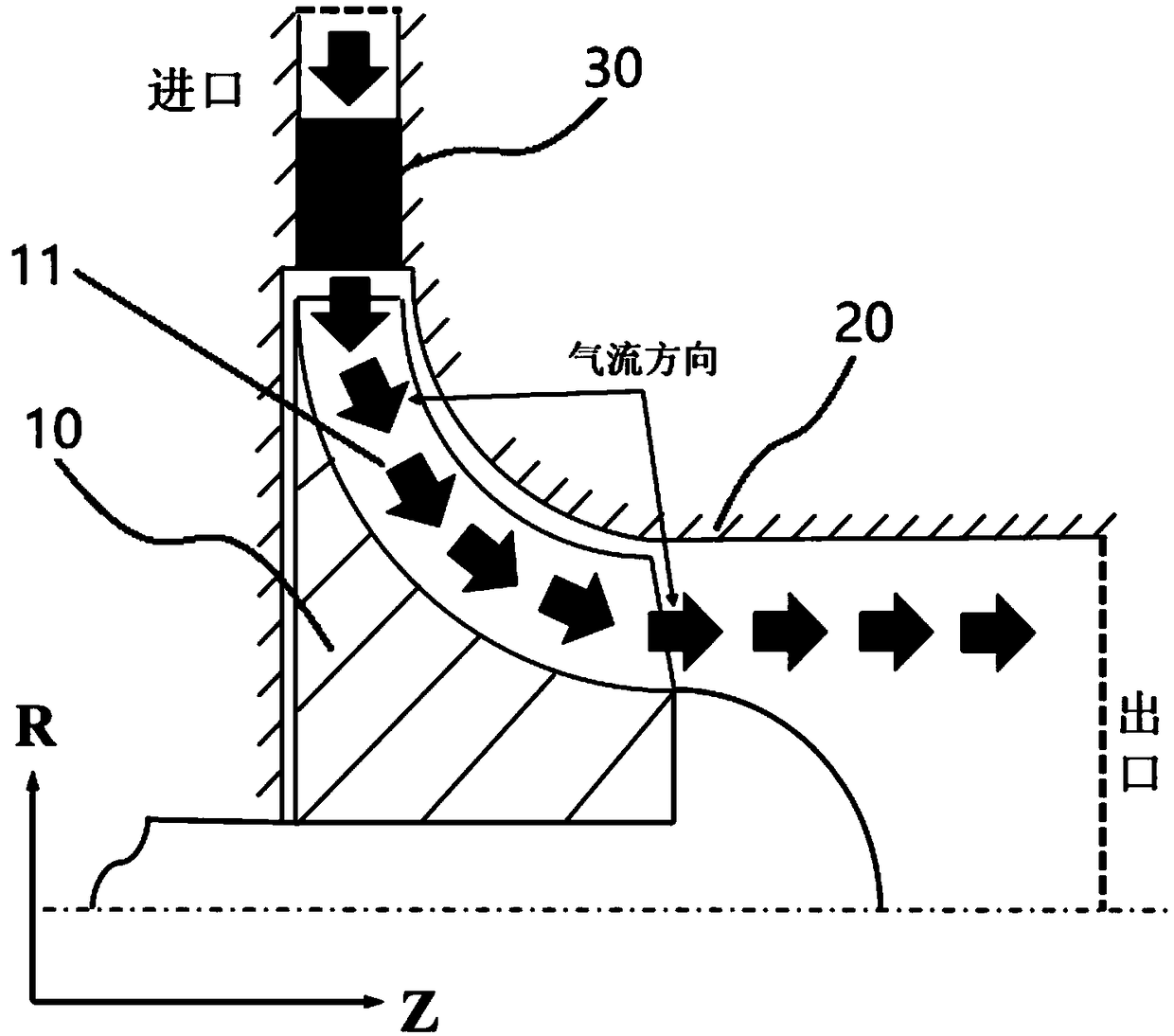
[0035] Such as figure 1 As shown, the radial flow turbine includes a radial flow impeller 10 and a casing 20. The radial flow impeller 10 is coaxially arranged in the casing 20. The radial flow impeller 10 is evenly distributed along its circumference with a plurality of radial flow blades 11. There is a tip clearance between the cassettes 20 . Turbine vanes 30 may further be provided upstream of the radial turbine. The radial flow turbine can be a centripetal type, a mixed flow type turbine, etc., and the radial flow turbine can be of a single-stage or multi-stage structure. The number, geometric shape, structural size and rotational speed of the radial flow turbines are determined with the design parameters. When the working fluid flows in the radi...


PUM


Abstract

The invention relates to a multi-factor coupling passive control technology inhibiting a blade tip clearance flow loss of a radial flow turbine. A bionic resistance reducing structure is arranged on the surface of a casing of an inlet area of the radial flow turbine; the blade tip clearance size of the turbine has a changing characteristic from an inlet of the turbine to an outlet; and the blade tip thickness distribution of blades has a changing characteristic from the inlet of the turbine to the outlet. The bionic resistance reducing structure is used for reducing the wall face friction losscaused by the scraping flow due to the relative movement between the top of a radial flow blade and the casing; the blade tip clearance size distribution and the blade tip thickness distribution bothchange in the direction from the inlet of the radial flow turbine to the outlet, so that the leakage flow caused by the pressure difference between the pressure face and the suction face of the bladetip of the radial flow blade is inhibited. The multi-factor coupling passive control technology inhibiting the blade tip clearance flow loss of the radial flow turbine can effectively control the blade tip clearance flow and the corresponding loss of the radial flow turbine, the pneumatic efficiency is improved, the utilizing efficiency of the energy of the radial flow turbine is effectively improved, and wide application in the fields of aerospace, transportation, compressed air energy storage and the like.

Description

technical field [0001] The invention belongs to the technical field of radial flow turbines in fluid machinery, and relates to the control of the flow loss in the tip clearance of the radial turbine, in particular to a multi-element coupling control structure for suppressing the flow loss in the tip clearance of the radial turbine. Background technique [0002] In recent years, radial flow turbines have been widely used and have various structural types, providing electricity and power for industrial production and public life. In order to make a unit volume of equipment output as much mechanical energy as possible under the same thermal parameters, it is necessary to improve the efficiency of the radial flow turbine. As a kind of fluid machinery, the impeller of the radial flow turbine and the casing have relative motion, and there is bound to be a gap between them, and this gap structure causes the working medium in the radial flow turbine to produce tip clearance flow los...

Claims


Application Information

Patent Timeline
Patent Type & Authority Applications(China)
IPC IPC(8): F01D11/08F01D25/24
CPCF01D11/08F01D25/24
Inventor 王星陈海生李文张雪辉朱阳历
Owner INST OF ENGINEERING THERMOPHYSICS - CHINESE ACAD OF SCI
Why Eureka
Try Eureka