Supercharge Your Innovation With Domain-Expert AI Agents!

Method for measuringoptical filterintrinsic phase frequency response

A technology of optical filter and phase-frequency response, which is applied in the direction of optical instrument testing, optical performance testing, measuring devices, etc., can solve the problems that the phase-frequency response cannot be obtained accurately, and it is difficult to eliminate accurately, so as to save hardware costs and simplify the system structure effect

Inactive Publication Date: 2018-12-18
成都市亿泰科技有限公司
View PDF4 Cites 0 Cited by
  • Summary
  • Abstract
  • Description
  • Claims
  • Application Information

AI Technical Summary

Problems solved by technology

However, the phase-frequency response obtained by its measurement usually includes the phase-frequency response of accessories such as pigtails in the optical device in addition to the intrinsic phase-frequency response of the optical device. response is much larger and difficult to accurately remove during calibration
Therefore, under normal circumstances, this technical solution can only perform relative measurements on the phase-frequency response of optical devices, and cannot accurately obtain the intrinsic phase-frequency response

Method used


Image

  • Method for measuringoptical filterintrinsic phase frequency response
  • Method for measuringoptical filterintrinsic phase frequency response
  • Method for measuringoptical filterintrinsic phase frequency response

Examples


Embodiment 1

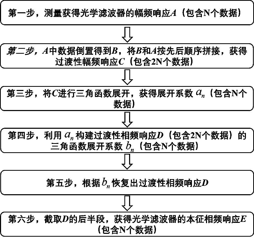
[0056] The following uses figure 1 The method for measuring the intrinsic phase-frequency response of an optical filter is shown, and the stimulated Brillouin scattering optical filter is taken as an example to further illustrate the present invention.

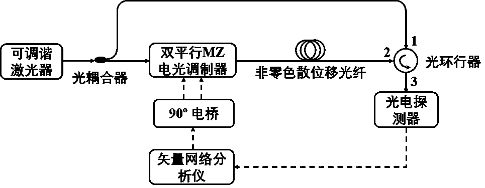
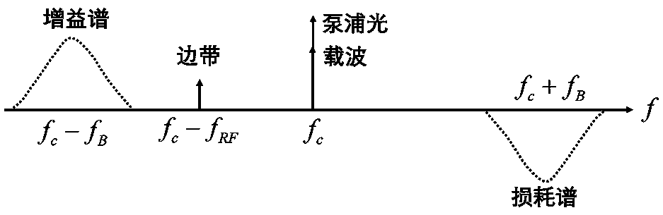
[0057] figure 2 The experimental device and principle for measuring the amplitude-frequency response and phase-frequency response of the stimulated Brillouin scattering optical filter in this embodiment are given. The device adopts an optical vector network analysis technology scheme based on optical single sideband modulation, which can simultaneously measure amplitude-frequency response and phase-frequency response. In this embodiment, the measured amplitude-frequency response is used to calculate the intrinsic phase-frequency response according to the method of the present invention, and the calculation result is compared with the measured phase-frequency response to verify the effectiveness of the method of the present ...

Embodiment 2

[0061] The following uses figure 1 The method for measuring the intrinsic phase-frequency response of an optical filter is shown, and the present invention is further illustrated by taking a phase-shifted fiber Bragg grating as an example.

[0062] Figure 7The experimental device and principle for measuring the amplitude-frequency response and phase-frequency response of the phase-shifted fiber Bragg grating in this embodiment are given. Like Embodiment 1, the optical vector network analysis technology scheme based on optical single sideband modulation is also used to measure the amplitude-frequency response and phase-frequency response simultaneously, and the amplitude-frequency response obtained by using the measurement is calculated according to the method of the present invention to obtain the intrinsic phase-frequency response , and compare the calculated results with the measured phase-frequency response to verify the effectiveness of the method of the present inventi...


PUM


Abstract

The invention belongs to the technical field of photoelectricity, and relates to a method for measuring optical filter intrinsic phase frequency response. Intrinsic phase frequency response can be obtained by calculating based on amplitude-frequency response measuring results of an optical filter. Compared with an existing optical vector network analysis method, in the method, no phases measuringmodule is required, system structure is simplified, the hardware cost is saved, and influence on intrinsic phase frequency response measuring results by phase frequency response of accessories such asan optical filter tail fiber is avoided. The intrinsic frequency response of the optical filter with minimum group delay can be accurately measured.

Description

technical field [0001] The invention relates to the field of optoelectronic technology, in particular to a method for measuring the intrinsic phase-frequency response of an optical filter. Background technique [0002] An optical filter is an optical device that only allows light of a specific wavelength to pass through, thereby controlling the spectrum of an optical signal. It has very important applications in the fields of optical communication, optical sensing, spectral analysis, and optical imaging. For some emerging technical fields, such as: all-optical signal processing, microwave photon technology, etc., the phase-frequency response characteristics of optical filters, like the amplitude-frequency response characteristics, play a decisive role in system performance. Therefore, it is very important to accurately characterize the magnitude-frequency and phase-frequency responses of optical filters, both for device development and system design. [0003] The amplitude-...

Claims


Application Information

Patent Timeline
IPC IPC(8): G01M11/02
CPCG01M11/00
Inventor 张旨遥高豪杨帆袁飞
Owner 成都市亿泰科技有限公司
Features
  • R&D
  • Intellectual Property
  • Life Sciences
  • Materials
  • Tech Scout
  • Unparalleled Data Quality
  • Higher Quality Content
  • 60% Fewer Hallucinations
Learn More